


19
WIRING
3
3.4
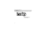
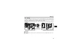
Wiring
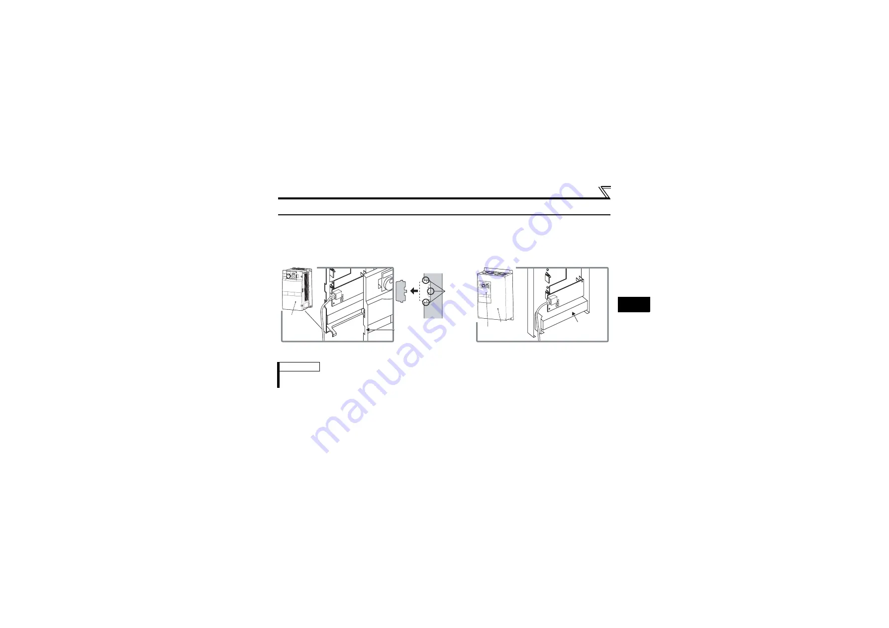
For wiring of the inverter which has one front cover, route wires between the control circuit terminal block
and front cover. If cables can not be routed between the control circuit terminal block and front cover (about
7mm), remove a hook of the front cover and use a space become available.
For wiring of the inverter which has front cover 1 and 2, use the space on the left side of the control circuit
terminal block.
REMARKS
⋅
When the hook of the inverter front cover is cut off for wiring, the protective structure (JEM1030) changes to open
type (IP00).
0
9
8
7 6 5
4
3
2
1
0
9
8
7 6 5
4
3
2
1
0
9
8
7 6 5
4
3
2
1
0
9
8
7 6 5
4
3
2
1
Cut off a hook on the inverter
front cover side surface.
(Cut off so that no portion is left.)
Cut off
with a
nipper,
etc.
Control circuit
terminal block
Front cover
Front cover 2
Front cover 1
Inverter which has one front cover
Inverter which has front cover 1 and 2
Summary of Contents for FR-F740-01160-EC
Page 103: ...97 MEMO ...


