III
CONTENTS
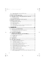
3.4.13 DU/PU, terminal FM/AM monitor display selection (Pr. 46 to Pr. 48, Pr. 50, Pr. 52, Pr. 54) ....... 86
3.4.14 Operation selection at instantaneous power failure (Pr. 57)........................................................ 89
3.4.15 Free parameter (Pr. 58, Pr. 59) ................................................................................................... 90
3.4.16 Key lock selection of operation panel(Pr. 61) .............................................................................. 90
3.4.17 Retry function (Pr. 65, Pr. 67 to Pr. 69) ....................................................................................... 91
3.4.18 Reset selection/disconnected PU detection/PU stop selection (Pr. 75) ...................................... 92
3.4.19 Parameter write disable selection (Pr. 77)................................................................................... 94
3.4.20 Current control (Pr. 82, Pr. 83) .................................................................................................... 95
3.4.21 Wiring and configuration of PU connector ................................................................................... 95
3.4.22 Initial settings and specifications of RS-485 communication (Pr. 117 to Pr. 124) ....................... 97
3.4.23 Mitsubishi inverter protocol (computer link communication)........................................................ 98
3.4.24 Initial setting and specification for the CC-Link communication function (Pr. 542 to Pr. 544) ... 109
3.4.25 Operation at a communication error (Pr. 500 to Pr. 502) .......................................................... 115
3.4.26 Communication EEPROM write selection (Pr. 342) .................................................................. 116
3.4.27 Setting of the parameter unit and operation panel (Pr. 145, Pr. 990, Pr. 991) .......................... 117
3.4.28 Terminal FM and AM calibration (calibration parameter C0 (Pr. 900), C1 (Pr. 901)) ................ 118
3.5 Parameter clear / All parameter clear ............................................ 120
3.6 Parameter copy and parameter verification...................................121
4.1 Troubleshooting...............................................................................124
4.2 Reset method of protective function..............................................124
4.3 List of fault and alarm indications..................................................125
4.4 Causes and corrective actions .......................................................126
4.5 Correspondences between digital and actual characters.............133
4.6 Check and clear of the faults history .............................................134
4.7 Check first when you have a trouble ..............................................136
5.2 Measurement of main circuit voltages, currents and powers ....... 145
HC2.book III ページ 2012年11月19日 月曜日 午前10時52分

