
F
R
-P
U0
7/
F
R
-P
U
07
BB
INST
RUCT
ION
M
A
NUAL
D
IN
VER
T
E
R
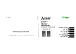
INVERTER
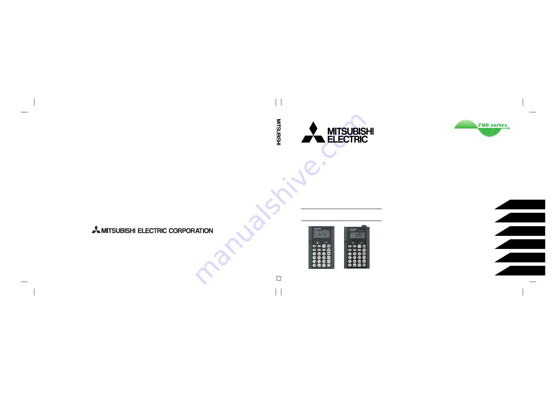
Option unit
INSTRUCTION MANUAL
INVERTER
HEAD OFFICE: TOKYO BUILDING 2-7-3, MARUNOUCHI, CHIYODA-KU, TOKYO 100-8310, JAPAN
1
2
3
4
6
5
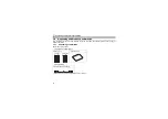
FR-PU07
FR-PU07BB
Parameter unit
IB(NA)-0600240ENG-D(0901) MEE
Printed in Japan
Specifications subject to change without notice.


