B-34
FX Series PLC User's Manual - Data Communication Edition
N:N Network
7 Creating Programs
7.1 Checking Contents of Related Devices
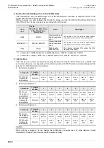
2. Devices for determining errors in the N:N Network
These devices are used for determining errors in the N:N Network. Use them to output link errors to the
outside and interlock sequence programs.
Different devices are used between the FX
0N
/FX
1S
Series and the FX
1N
/FX
1NC
/FX
2N
/FX
2NC
/FX
3S
/FX
3G
/
FX
3GC
/FX
3U
/FX
3UC
Series. Use devices according to the PLCs used.
*1.
Station No. 1: M505, Station No. 2: M506, Station No. 3: M507... Station No. 7: M511
*2.
Station No. 1: M8184, Station No. 2: M8185, Station No. 3: M8186... Station No. 7: M8190
3. Link devices
These devices are used for sending and receiving information among the PLCs. The device numbers used
and number of devices vary depending on the station number set in D8176 (station number settings) and the
pattern set in D8178 (refresh range setting).
1) In the case of pattern 0
2) In the case of pattern 1
3) In the case of pattern 2
Caution
When creating a program, do not change the information in devices used by other stations. If such
information is changed, other stations will not operate normally.
Device
Name
Description
FX
0N
,
FX
1S
FX
1N
, FX
1NC
, FX
2N
, FX
2NC,
FX
3S
, FX
3G
, FX
3GC
,
FX
3U
, FX
3UC
M504
M8183
Master station data
transfer sequence
error
This device turns ON when a data transfer
sequence error occurs in the master station.
M505 to M511
*1
M8184 to M8190
*2
Slave station data
transfer sequence
error
This device turns ON when a data transfer
sequence error occurs in a slave station.
M503
M8191
Data transfer
sequence ON
This device remains ON while the N:N
Network is operating.
Station No.
0 (master
station)
1
2
3
4
5
6
7
Word device
(4 points for
each station)
D0 to D3
D10 to
D13
D20 to
D23
D30 to
D33
D40 to
D43
D50 to
D53
D60 to
D63
D70 to
D73
Station No.
0 (master
station)
1
2
3
4
5
6
7
Bit devices
(32 points for
each station)
M1000 to
M1031
M1064 to
M1095
M1128 to
M1159
M1192 to
M1223
M1256 to
M1287
M1320 to
M1351
M1384 to
M1415
M1448 to
M1479
Word device
(4 points for
each station)
D0 to D3
D10 to
D13
D20 to
D23
D30 to
D33
D40 to
D43
D50 to
D53
D60 to
D63
D70 to
D73
Station No.
0 (master
station)
1
2
3
4
5
6
7
Bit devices
(64 points for
each station)
M1000 to
M1063
M1064 to
M1127
M1128 to
M1191
M1192 to
M1255
M1256 to
M1319
M1320 to
M1383
M1384 to
M1447
M1448 to
M1511
Word device
(8 points for
each station)
D0 to D7
D10 to
D17
D20 to
D27
D30 to
D37
D40 to
D47
D50 to
D57
D60 to
D67
D70 to
D77
Summary of Contents for FX-485ADP
Page 2: ......
Page 120: ...B 2 FX Series PLC User s Manual Data Communication Edition N N Network ...
Page 188: ...C 2 FX Series PLC User s Manual Data Communication Edition Parallel Link ...
Page 244: ...D 2 FX Series PLC User s Manual Data Communication Edition Computer Link ...
Page 344: ...E 2 FX Series PLC User s Manual Data Communication Edition Inverter Communication ...
Page 700: ...H 2 FX Series PLC User s Manual Data Communication Edition Programming Communication ...
Page 752: ...I 2 FX Series PLC User s Manual Data Communication Edition Remote Maintenance ...
Page 817: ......

