B-36
FX Series PLC User's Manual - Data Communication Edition
N:N Network
7 Creating Programs
7.2 Creating Programs for Master Station (Station No. 0)
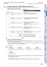
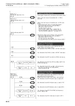
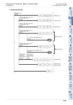
This program is required to write information from the
master station to each slave station.
Program for writing link devices
(master station
→
slave station)
FNC 12
MOV
K4M100
K4M1010
FNC 12
MOV
D100
D0
Station No. 1
Data transfer
sequence error
X002
M10
M8000
M1064
M1065
M1066
M8184
FNC 12
MOV
K4M1070
K4Y020
FNC 12
MOV
D10
D110
X000
Y011
M1000
M1001
M1002
M0
M15
The information from X000 is written to M1000 (link device).
The information from X002 is written to M1001 (link device).
The information from M10 is written to M1002 (link device).
The information from M100 to M115 is written to M1010 to
M1025 (link devices).
The information from D100 is written to D0 (link device).
* In pattern 0, bit devices are not applicable.
Use word devices only.
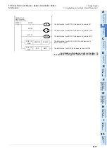
This program is required to read information from each
slave station to the master station.
Monitor link errors in each slave station, and read them.
Program for reading link devices
(master station
←
slave station)
The information from M1064 (link device) is read to M0.
The information from M1065 (link device) is read to Y011.
The information from M1066 (link device) is read to M15.
The information from M1070 to M1085 (link devices) is
read to Y020 to Y037.
The information from D10 (link device) is read to D110.
M8184
M8185
M8191
Station No. 1
Data transfer sequence error
Station No. 2
Data transfer sequence error
Data transfer sequence ON
Y000
Y001
Y010
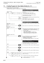
Program for indicating link errors
When a link error occurs in the station No. 1, Y000 is
set to ON.
When a link error occurs in the station No. 2, Y001 is set
to ON.
• Create this step for each connected slave station.
Note that the devices to be used are different
depending on the PLC Series.
For FX
0N
and FX
1S
Series:
M505 to M511 (station No. 1 to station No. 7)
For any series other than FX
0N
and FX
1S
Series:
M8184 to M8190 (station No. 1 to station No. 7)
While the N:N Network is executed, Y010 remains ON.
• Note that the devices to be used are different
depending on the PLC Series.
For FX
0N
and FX
1S
Series: M503
For any series other than FX
0N
and FX
1S
Series: M8191
This program is required to indicate the N:N Network status.
Summary of Contents for FX-485ADP
Page 2: ......
Page 120: ...B 2 FX Series PLC User s Manual Data Communication Edition N N Network ...
Page 188: ...C 2 FX Series PLC User s Manual Data Communication Edition Parallel Link ...
Page 244: ...D 2 FX Series PLC User s Manual Data Communication Edition Computer Link ...
Page 344: ...E 2 FX Series PLC User s Manual Data Communication Edition Inverter Communication ...
Page 700: ...H 2 FX Series PLC User s Manual Data Communication Edition Programming Communication ...
Page 752: ...I 2 FX Series PLC User s Manual Data Communication Edition Remote Maintenance ...
Page 817: ......

