C-47
FX Series PLC User's Manual - Data Communication Edition
Parallel Link
8 Practical Program Examples
8.1 Practical Example 1 (Regular Parallel Link Mode)
A
Comm
on I
te
ms
B
N:
N N
etwo
rk
C
Paral
le
l Li
nk
D
Com
puter Li
nk
E
In
verter
C
omm
uni
cation
F
N
on-Proto
col
C
ommunicati
on
(R
S/RS
2 Instru
ction
)
G
No
n-
Protoc
ol
Co
mmuni
ca
tion
(FX
2N
-2
32IF)
H
Programm
ing
Comm
uni
cation
I
Re
mo
te
Ma
intenance
Apx.A
D
isco
nti
nued
models
8. Practical Program Examples
This chapter shows practical programs examples.
8.1
Practical Example 1 (Regular Parallel Link Mode)
When many link devices are required, use the regular parallel link mode.
8.1.1
System configuration example
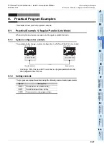
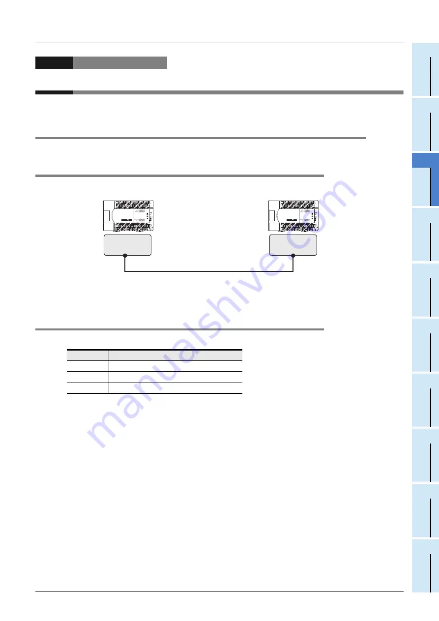
The example below shows a system configuration in which two FX
2N
PLCs are linked.
- Link range: 100-bit devices and 10-word devices (regular parallel link mode)
- Error judgement time: 500 ms
8.1.2
Setting contents
The program examples shown later adopt the following communication parameters:
Device
Description
M8070
Parallel link master station setting
M8071
Parallel link slave station setting
D8070
Communication error judgement time
FX
2N
-485-BD
FX
2N
-485-BD
FX
2N
PLC
FX
2N
PLC
Master station
Slave station
Summary of Contents for FX-485ADP
Page 2: ......
Page 120: ...B 2 FX Series PLC User s Manual Data Communication Edition N N Network ...
Page 188: ...C 2 FX Series PLC User s Manual Data Communication Edition Parallel Link ...
Page 244: ...D 2 FX Series PLC User s Manual Data Communication Edition Computer Link ...
Page 344: ...E 2 FX Series PLC User s Manual Data Communication Edition Inverter Communication ...
Page 700: ...H 2 FX Series PLC User s Manual Data Communication Edition Programming Communication ...
Page 752: ...I 2 FX Series PLC User s Manual Data Communication Edition Remote Maintenance ...
Page 817: ......


