E-47
FX Series PLC User's Manual - Data Communication Edition
Inverter Communication
4 Wiring
4.9 Grounding
A
Comm
on I
te
ms
B
N:
N N
etwo
rk
C
Paral
le
l Li
nk
D
Com
puter Li
nk
E
In
verter
C
omm
uni
cation
F
N
on-Proto
col
C
ommunicati
on
(R
S/RS
2 Instru
ction
)
G
No
n-
Protoc
ol
Co
mmuni
ca
tion
(FX
2N
-2
32IF)
H
Programm
ing
Comm
uni
cation
I
Re
mo
te
Ma
intenance
Apx.A
D
isco
nti
nued
models
4.8.6
Switching of 1 pair / 2 paired wiring (FX
3G
-485-BD-RJ)
The FX
3G
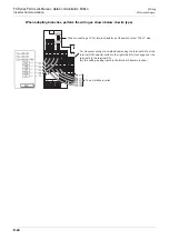
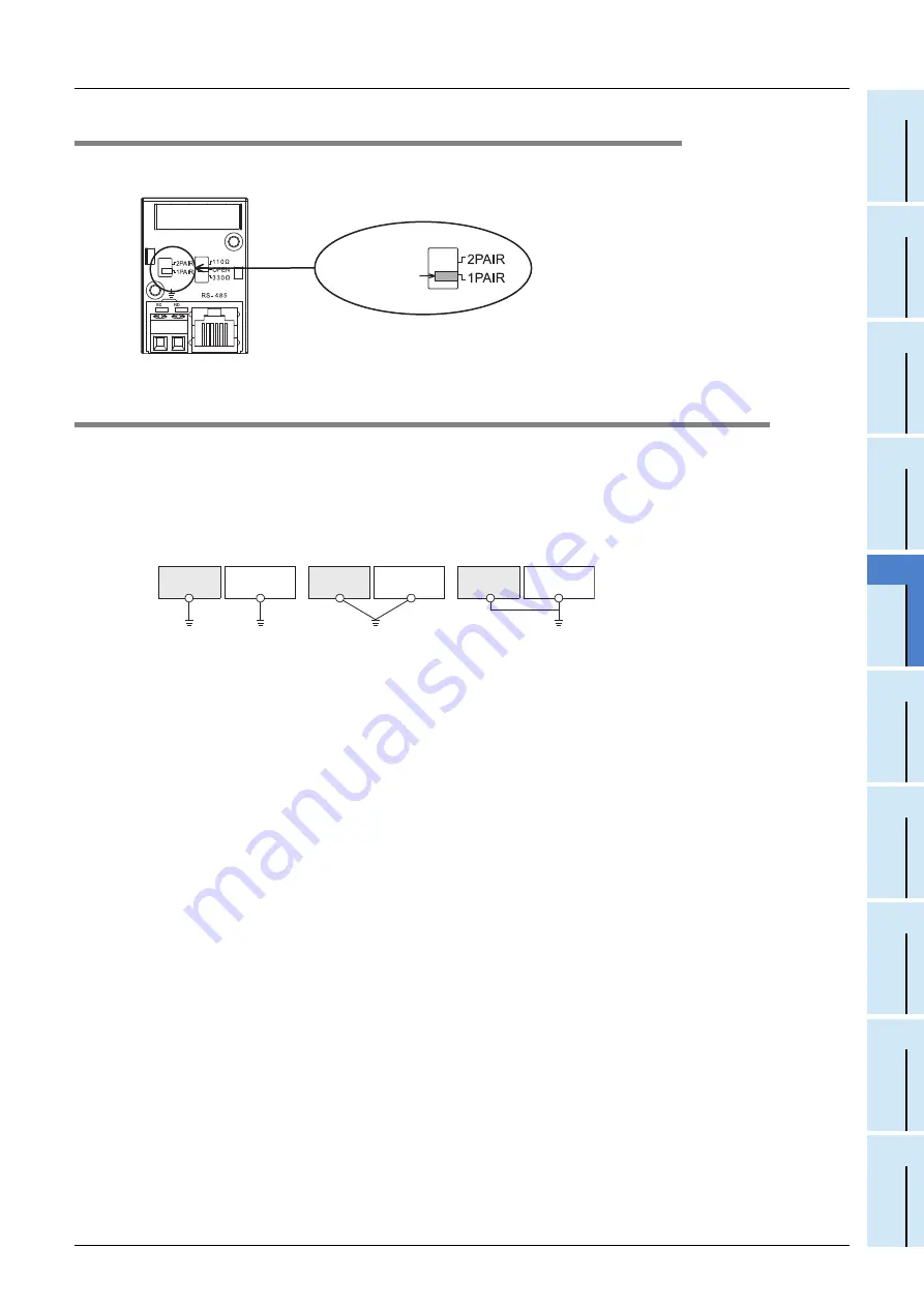
-485-BD-RJ has a built-in wiring circuit switch.
Set the wiring circuit switch to 1 pair / 2 pair.
4.9
Grounding
Grounding should be performed as stated below.
• The grounding resistance should be 100
or less.
• Independent grounding should be performed for best results.
When independent grounding can not be performed, perform "shared grounding" as shown in the following
figure.
For details, refer to the Hardware Edition of each series.
• The grounding wire size should be AWG 14 (2 mm
2
) or larger.
• The grounding point should be close to the PLC, and all grounding wires should be as short as possible.
Wiring circuit
switch
PLC
Other
equipment
PLC
Other
equipment
PLC
Other
equipment
Shared grounding
Good condition
Common grounding
Not allowed
Independent grounding
Best condition
Summary of Contents for FX-485ADP
Page 2: ......
Page 120: ...B 2 FX Series PLC User s Manual Data Communication Edition N N Network ...
Page 188: ...C 2 FX Series PLC User s Manual Data Communication Edition Parallel Link ...
Page 244: ...D 2 FX Series PLC User s Manual Data Communication Edition Computer Link ...
Page 344: ...E 2 FX Series PLC User s Manual Data Communication Edition Inverter Communication ...
Page 700: ...H 2 FX Series PLC User s Manual Data Communication Edition Programming Communication ...
Page 752: ...I 2 FX Series PLC User s Manual Data Communication Edition Remote Maintenance ...
Page 817: ......

