E-102
FX Series PLC User's Manual - Data Communication Edition
Inverter Communication
9 Creating Programs (FX3S, FX3G, FX3GC, FX3U, FX3UC)
9.3 Common Items in Inverter Communication Instructions
9.3.4
Cautions on programming
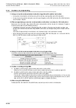
1. Using an inverter communication instruction together with another instruction
• An inverter communication instruction using ch1 cannot be used together with a RS instruction.
• An inverter communication instruction cannot be used together with a RS2 instruction if the RS2 instruction
uses the same channel.
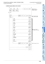
2. When programming an inverter communication instruction in a state of a STL instruction
Make sure to let the state relay remain ON until communication with an inverter is completed. Program a
sequence while observing the following cautions
• Add M8029 (instruction execution complete flag) ON condition to the state relay transfer condition, and
provide such interlock that the state relay ON/OFF status does not change during communication with an
inverter.
If the state changes during communication, communication may not be performed normally.
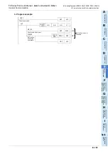
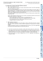
• When resetting many state relays all at once using the ZRST (FNC 40) instruction, etc., make sure that the
M8151 or M8156 (communication port busy) condition is OFF.
3. Using an inverter communication instruction in a program flow
An inverter communication instruction cannot be used in the following program flows
4. Caution on writing during RUN
1) Condition in which inverter communication instruction can be written:
While the PLC is in the STOP status, inverter communication instruction can be written during RUN.
2) Condition in which inverter communication instruction cannot be written:
Inverter communication instruction cannot be written during RUN.
If an inverter communication instruction is written during RUN during communication or if an inverter
communication instruction is deleted while in RUN, communication may be disabled after that. (In such a
case, set the PLC to STOP, and then to RUN mode again to initialize the status.)
5. When using the E500 Series
Parameters Nos. 922 and 923 in the E500 Series cannot be used in inverter communication.
Program flow disabling the inverter communication
instruction
Remarks
Between CJ and P instructions
Conditional jump
Between FOR and NEXT instructions
Repeat
Between P and SRET instructions
Subroutine
Between I and IRET instructions
Interrupt routine
SET
M0
Reset input
State relays S0 to S999
are reset all at once.
RST
M0
S0
S999
FNC 40
ZRST
M0
X000
M8151
Communication
port busy
Summary of Contents for FX-485ADP
Page 2: ......
Page 120: ...B 2 FX Series PLC User s Manual Data Communication Edition N N Network ...
Page 188: ...C 2 FX Series PLC User s Manual Data Communication Edition Parallel Link ...
Page 244: ...D 2 FX Series PLC User s Manual Data Communication Edition Computer Link ...
Page 344: ...E 2 FX Series PLC User s Manual Data Communication Edition Inverter Communication ...
Page 700: ...H 2 FX Series PLC User s Manual Data Communication Edition Programming Communication ...
Page 752: ...I 2 FX Series PLC User s Manual Data Communication Edition Remote Maintenance ...
Page 817: ......

