E-105
FX Series PLC User's Manual - Data Communication Edition
Inverter Communication
9 Creating Programs (FX3S, FX3G, FX3GC, FX3U, FX3UC)
9.5 Inverter Operation Control Instruction (PLC
Inverter) [FNC271 / IVDR]
A
Comm
on I
te
ms
B
N:
N N
etwo
rk
C
Paral
le
l Li
nk
D
Com
puter Li
nk
E
In
verter
C
omm
uni
cation
F
N
on-Proto
col
C
ommunicati
on
(R
S/RS
2 Instru
ction
)
G
No
n-
Protoc
ol
Co
mmuni
ca
tion
(FX
2N
-2
32IF)
H
Programm
ing
Comm
uni
cation
I
Re
mo
te
Ma
intenance
Apx.A
D
isco
nti
nued
models
9.5
Inverter Operation Control Instruction (PLC
Inverter) [FNC271 / IVDR]
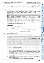
This instruction writes a control value required to operate an inverter from the PLC to the inverter.
9.5.1
Function and operation
When an "instruction code" specified for computer link operation in the inverters is specified in the IVDR
(FNC271) instruction, the value specified in
is written to the specified item of the inverter.
1. Applicable devices
1: Only available for FX
3G
, FX
3GC
, FX
3U
and FX
3UC
PLCs.
2: Only available for FX
3U
and FX
3UC
PLCs.
2. Program example
9.5.2
Inverter instruction codes
The table below shows inverter instruction codes which can be specified in
.
For the instruction codes, refer to the pages explaining computer link in detail in each inverter manual.
*1.
The instruction code "HFD (inverter reset)" does not request a response from the inverter.
Accordingly, even if inverter reset is executed to a station number at which an inverter is not
connected, error does not occur.
It takes about 2.2 seconds to complete execution of inverter reset.
*2.
When resetting the inverter, please specify H9696 as the operand
of the IVDR instruction.
Do not use H9966.
*3.
Please write "0" to instruction code HFF (Link parameter expansion setting) just before the IVDR
instruction when writing frequency.
When "0" is not written, writing of the frequency may not be executed normally.
Oper-
and
Type
Bit Devices
Word Devices
Others
System/User
Digit Specification
System/User
Special
Unit
Index
Con-
stant
Real
Number
Charac-
ter String
Pointer
X Y M T C S D
.b KnX KnY KnM KnS T C D
R U
\G
V Z Modify K H
E
"
"
P
1
2
1
2
1
2
n
Inverter Instruction
code (hexadecimal)
Write contents
Applicable inverter
F800, A800, F700,
A700, E700, D700
V500 F500, A500
E500, S500
HFB
Operation mode
HF3
Special monitor selection No.
—
HF9
Run command (expansion)
—
—
—
HFA
Run command
HEE
Set frequency write (EEPROM)
*3
HED
Set frequency write (RAM)
*3
HFD
*1
Inverter reset
*2
HF4
Alarm definition batch clear
—
HFC
Parameter all clear
HFC
User clear
—
—
—
HFF
Link parameter expansion setting
S
3
S
1
S
2
S
3
M0
FNC271
IVDR
K6
HFA
K2M50
S
1
S
2
S
3
Command
contact
Inverter station number: 0 to 31
Inverter instruction code (hexadecimal)
Value written to inverter
K1
n
Communication channel K1:ch1
K2:ch2
S
2
S
2
S
3
Summary of Contents for FX-485ADP
Page 2: ......
Page 120: ...B 2 FX Series PLC User s Manual Data Communication Edition N N Network ...
Page 188: ...C 2 FX Series PLC User s Manual Data Communication Edition Parallel Link ...
Page 244: ...D 2 FX Series PLC User s Manual Data Communication Edition Computer Link ...
Page 344: ...E 2 FX Series PLC User s Manual Data Communication Edition Inverter Communication ...
Page 700: ...H 2 FX Series PLC User s Manual Data Communication Edition Programming Communication ...
Page 752: ...I 2 FX Series PLC User s Manual Data Communication Edition Remote Maintenance ...
Page 817: ......


