F-51
FX Series PLC User's Manual - Data Communication Edition
Non-Protocol Communication (RS/RS2 Instruction)
6 Creating Programs (RS Instruction)
6.2 How to Use RS Instruction
A
Comm
on I
te
ms
B
N:
N N
etwo
rk
C
Paral
le
l Li
nk
D
Com
puter Li
nk
E
In
verter
C
omm
uni
cation
F
N
on-Proto
col
C
ommunicati
on
(R
S/RS
2 Instru
ction
)
G
No
n-
Protoc
ol
Co
mmuni
ca
tion
(FX
2N
-2
32IF)
H
Programm
ing
Comm
uni
cation
I
Re
mo
te
Ma
intenance
Apx.A
D
isco
nti
nued
models
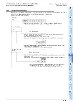
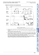
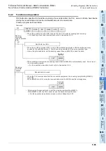
3. Operation of the time-out check flag (which is not provided in FX
2N
PLC before Ver. 2.00,
and FX
2
(FX), FX
2C
, FX
0N
PLCs)
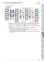
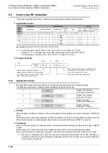
When data receiving is suspended, counting of the timeout time is started immediately. If the PLC does not
receive the next set of data within the time-out time setting set by D8129, the time-out check flag (M8129) is
set to ON. At this time, the receiving complete flag (M8123) is set to ON also.
The time-out time setting (D8129) can be set to a value from 1 to 255 (10 ms to 2550 ms).
The time-out check flag (M8129) does not turn OFF automatically.
Set it to OFF in the sequence program. (When M8123 is set to OFF, M8129 is also set to OFF.)
Using this function, the PLC can receive data from equipment where the amount of send data varies without
the terminator.
4. When the control line is set to interlink mode
When interlink mode is selected as the communication format, the following sequence is adopted from the
start of receiving to completion:
1) When the amount of data already received becomes "number of bytes to be received -30", the control line
ER (DTR) turns OFF.
When the control line ER (DTR) turns OFF, the external equipment should suspend data sending.
After the control line ER (DTR) turns OFF, the PLC can receive up to 30 characters (bytes).
2) When the external equipment suspends data sending, the PLC sets the time-out check flag (M8129) and
receiving complete flag (M8123) to ON after the time-out time setting (D8129).
Move the received data in a sequence program, and then set the receiving complete flag (M8123) and
time-out check flag (M8129) to OFF.
3) When the receiving complete flag (M8123) is set to OFF, the control line ER (DTR) turns ON.
When the control line ER (DTR) turns ON, resume sending data from the external equipment.
4) Repeat steps 1) to 3) until data receiving is completed.
5. Cautions on receiving
When receiving data, observe the following cautions:
1) While the receiving complete flag (M8123) is ON, the PLC cannot receive the next set of data.
When the receiving complete flag is set to OFF, the PLC waits to receive.
2) If the RS instruction is driven while the amount of received data "n" is "0", the operation of the receiving
complete flag (M8123) varies depending on the PLC as follows:
• FX
1S
, FX
1N
, FX
1NC
PLCs
The receiving complete flag (M8123) remains OFF even after the RS instruction is driven, but the PLC
does not wait to receive.
• FX
2N
, FX
2NC
, FX
3S
, FX
3G
, FX
3GC
, FX
3U
, FX
3UC
PLCs
The receiving complete flag (M8123) turns ON after the RS instruction is driven.
To make the PLC wait to receive, set the amount of received data "n" to "1" or more, and set the receiving
complete flag (M8123) to OFF from ON.
Receive data is suspended.
Set to OFF in sequence program.
Receiving
D8129
10 ms
Data
ON
Timeout determination
M8129
ON
Receiving complete
M8123
Summary of Contents for FX-485ADP
Page 2: ......
Page 120: ...B 2 FX Series PLC User s Manual Data Communication Edition N N Network ...
Page 188: ...C 2 FX Series PLC User s Manual Data Communication Edition Parallel Link ...
Page 244: ...D 2 FX Series PLC User s Manual Data Communication Edition Computer Link ...
Page 344: ...E 2 FX Series PLC User s Manual Data Communication Edition Inverter Communication ...
Page 700: ...H 2 FX Series PLC User s Manual Data Communication Edition Programming Communication ...
Page 752: ...I 2 FX Series PLC User s Manual Data Communication Edition Remote Maintenance ...
Page 817: ......

