F-64
FX Series PLC User's Manual - Data Communication Edition
Non-Protocol Communication (RS/RS2 Instruction)
8 Creating Programs (RS2 Instruction)
8.2 How to Use RS2 Instruction
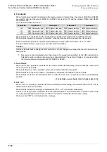
2. Terminator
When "terminator provided" is selected in the communication format settings, the values of D8382 and D8383
are used for ch0, and the values of D8412 and D8413 are used for ch1, and the values of D8432 and D8433
are used for ch2.
Up to four terminators can be set.
When data is sent, the data set in the devices above is added at the end of the specified send data.
When data is received, receiving is completed
*1
when the data set in the devices above is received.
Even if "terminator provided" is selected, terminators are not provided if terminator 1 is set to "00H".
The area before 00H (
in 1-byte units
) is used to set the terminators.
Caution
Set the terminator before driving the RS2 instruction. Do not change the setting while the RS2 instruction is
being driven.
*1.
Receiving is also completed when the amount of received data specified by the RS2 instruction is
finished receiving or when data receiving is suspended and the next set of data is not received within
the time-out time setting device (D8379, D8409 or D8429).
3. Sum check
When "sum check provided" is selected in the communication format setting, the sum check is executed for
the sent and received data.
When selecting "sum check provided", make sure to select "terminator provided".
When data is sent, the sum of "data" + "terminator" is calculated, and added to the send data.
When data is received, it is checked whether or not the received sum is equivalent to the sum calculated by
the PLC.
For details on sum check, refer to Subsection 8.2.6.
4. CR + LF
When "CR + LF provided" is selected in the communication format setting, the character code of "CR + LF" is
added at the end of the send data.
When data is received, receiving is completed when "CR + LF" is received continuously.
However, receiving is also completed when the specified amount of received data is received or when data
receiving is suspended and the next set of data is not received within the time-out time setting.
Make sure that "CR" is not included in the message.
Terminator
Terminator 1
Terminator 2
Terminator 3
Terminator 4
ch0
D8382 (lowest-order byte)
D8382 (highest-order byte)
D8383 (lowest-order byte)
D8383 (highest-order byte)
ch1
D8412 (lowest-order byte)
D8412 (highest-order byte)
D8413 (lowest-order byte)
D8413 (highest-order byte)
ch2
D8432 (lowest-order byte)
D8432 (highest-order byte)
D8433 (lowest-order byte)
D8433 (highest-order byte)
Summary of Contents for FX-485ADP
Page 2: ......
Page 120: ...B 2 FX Series PLC User s Manual Data Communication Edition N N Network ...
Page 188: ...C 2 FX Series PLC User s Manual Data Communication Edition Parallel Link ...
Page 244: ...D 2 FX Series PLC User s Manual Data Communication Edition Computer Link ...
Page 344: ...E 2 FX Series PLC User s Manual Data Communication Edition Inverter Communication ...
Page 700: ...H 2 FX Series PLC User s Manual Data Communication Edition Programming Communication ...
Page 752: ...I 2 FX Series PLC User s Manual Data Communication Edition Remote Maintenance ...
Page 817: ......

