F-89
FX Series PLC User's Manual - Data Communication Edition
Non-Protocol Communication (RS/RS2 Instruction)
11 Troubleshooting
11.5 Checking the Absence/Presence of Errors
A
Comm
on I
te
ms
B
N:
N N
etwo
rk
C
Paral
le
l Li
nk
D
Com
puter Li
nk
E
In
verter
C
omm
uni
cation
F
N
on-Proto
col
C
ommunicati
on
(R
S/RS
2 Instru
ction
)
G
No
n-
Protoc
ol
Co
mmuni
ca
tion
(FX
2N
-2
32IF)
H
Programm
ing
Comm
uni
cation
I
Re
mo
te
Ma
intenance
Apx.A
D
isco
nti
nued
models
11.4.1 Checking communication port settings (in FX
3S
, FX
3G
, FX
3GC
, FX
3U
and FX
3UC
PLCs)
1. Checking the operation mode
In FX
3S
, FX
3G
, FX
3GC
, FX
3U
and FX
3UC
PLCs, the communication port operation status can be checked.
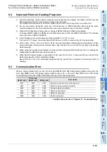
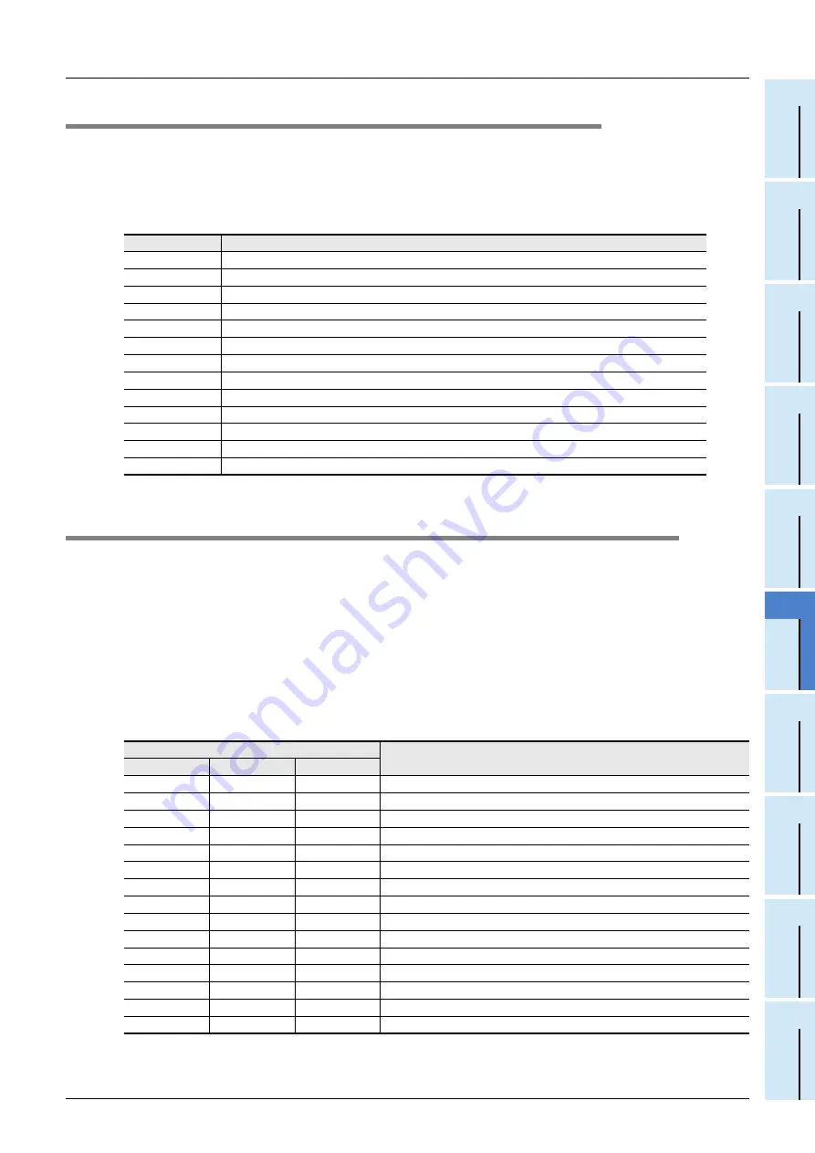
D8389 stores the communication type code currently adopted in communication port ch0.
D8419 stores the communication type code currently adopted in communication port ch1.
D8439 stores the communication type code currently adopted in communication port ch2.
The table below shows the contents of the communication type codes.
If the operation mode is different, check the parameters and sequence programs.
11.5
Checking the Absence/Presence of Errors
1. Checking for communication errors
When a communication error occurs, the serial communication error flag turns ON.
When the communication port ch0 is used in FX
3G
, FX
3GC
PLCs, M8062 turns ON.
In all PLCs except FX
3G
, FX
3GC
, FX
3U
and FX
3UC
PLCs using the communication port, M8063 turns ON.
For FX
3G
, FX
3GC
, FX
3U
and FX
3UC
PLCs using the communication port ch1, M8063 turns ON.
When communication port ch2 is used in FX
3G
, FX
3GC
, FX
3U
and FX
3UC
PLCs, M8438 turns ON.
When the serial communication error flag turns ON, D8062, D8063 or D8438 stores the corresponding error code.
Available channels vary depending on the main unit.
For details, refer to Section 3.2.
2. Checking the error code
When the serial communication error flag turns ON, a corresponding error code shown below is stored in
D8063 or D8438.
When an error code above is stored, check the following items:
• Wiring
• Parameter settings
Code
Description
0
Programming communication
1
PP modem mode
2
Protocol dedicated to computer link
3
N:N Network
4
RS instruction
5
RS2 instruction
6
Parallel link
7
Inverter instruction
8
The variable analog potentiometer expansion board is used.
9
MODBUS communication
10
CF-ADP
11
ENET-ADP
12
Input/output expansion board is used.
Error code
Contents of error
ch0 (D8062)
ch1 (D8063)
ch2 (D8438)
6201
6301
3801
Parity error, overrun error or framing error
6202
6302
3802
Defective communication character
6203
6303
3803
Communication data sum mismatch
6204
6304
3804
Defective data format
6205
6305
3805
Defective command
6206
6306
3806
Monitoring timeout
—
6307
3807
Modem initialization error
—
6308
3808
N:N Network parameter error
—
6309
3809
N:N Network setting error
—
6312
3812
Parallel link parameter error
—
6313
3813
Parallel link sum error
—
6314
3814
Parallel link format error
—
6320
3820
Inverter communication error
—
6330
3830
Memory access error
—
6340
3840
Special adapter connection error
Summary of Contents for FX-485ADP
Page 2: ......
Page 120: ...B 2 FX Series PLC User s Manual Data Communication Edition N N Network ...
Page 188: ...C 2 FX Series PLC User s Manual Data Communication Edition Parallel Link ...
Page 244: ...D 2 FX Series PLC User s Manual Data Communication Edition Computer Link ...
Page 344: ...E 2 FX Series PLC User s Manual Data Communication Edition Inverter Communication ...
Page 700: ...H 2 FX Series PLC User s Manual Data Communication Edition Programming Communication ...
Page 752: ...I 2 FX Series PLC User s Manual Data Communication Edition Remote Maintenance ...
Page 817: ......

