F-96
FX Series PLC User's Manual - Data Communication Edition
Non-Protocol Communication (RS/RS2 Instruction)
12 Related Data
12.3 Related Devices (RS2 Instruction)
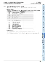
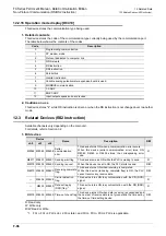
12.2.16 Operation mode display [D8419]
This device stores the communication type being used.
1. Detailed contents
This device stores the code of the communication type currently being used by the communication port.
The table below shows the contents of the codes.
2. Cautions on use
This device stores "4" while RS instruction is driven or when the RS instruction is not changed over to another
mode.
12.3
Related Devices (RS2 Instruction)
Available channels vary depending on the main unit.
For details, refer to Section 3.2.
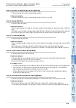
1. Bit devices
R: Read only
W: Write only
R/W: Read or Write
*1.
FX
3U
, FX
3UC
PLCs Ver. 2.30 or later, and FX
3S
, FX
3G
, FX
3GC
PLCs is applicable.
Code
Description
0
Programming communication
1
PP modem mode
2
Protocol dedicated to computer link
3
N:N Network
4
RS instruction
5
RS2 instruction
6
Parallel link
7
Inverter instruction
8
Variable analog potentiometer expansion board is used.
9
MODBUS communication
10
CF-ADP
11
ENET-ADP
12
Input/output expansion board is used.
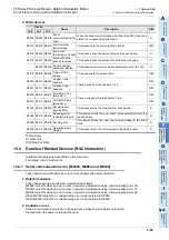
Device
Name
Description
R/W
ch0
ch1
ch2
M8062 M8063 M8438
Serial
communication
error
This device turns ON when a communication error occurs.
When this device (serial communication error) turns ON,
D8062, D8063 or D8438 stores the corresponding error
code.
R
M8371 M8401 M8421 Sending wait flag
This device remains ON while the PLC is waiting to send.
R
M8372 M8402 M8422 Sending request
When this device is set to ON, the PLC starts to send.
R/W
M8373 M8403 M8423
Receiving complete
flag
This device turns ON when receiving is completed.
While this device (receiving complete flag) is ON, the PLC
cannot receive any receive data.
R/W
—
M8404 M8424
Carrier detection
flag
This device turns ON in synchronization with the CD (DCD)
signal.
R
—
M8405 M8425
Data set ready
(DSR) flag
*1
This device turns ON in synchronization with the DR (DSR)
signal.
R
M8379 M8409 M8429 Time-out check flag
This device turns ON when data receiving is suspended and
the next set of receive data is not given within the time set by
the time-out time setting device.
R/W
Summary of Contents for FX-485ADP
Page 2: ......
Page 120: ...B 2 FX Series PLC User s Manual Data Communication Edition N N Network ...
Page 188: ...C 2 FX Series PLC User s Manual Data Communication Edition Parallel Link ...
Page 244: ...D 2 FX Series PLC User s Manual Data Communication Edition Computer Link ...
Page 344: ...E 2 FX Series PLC User s Manual Data Communication Edition Inverter Communication ...
Page 700: ...H 2 FX Series PLC User s Manual Data Communication Edition Programming Communication ...
Page 752: ...I 2 FX Series PLC User s Manual Data Communication Edition Remote Maintenance ...
Page 817: ......

