F-98
FX Series PLC User's Manual - Data Communication Edition
Non-Protocol Communication (RS/RS2 Instruction)
12 Related Data
12.4 Details of Related Devices (RS2 Instruction)
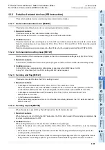
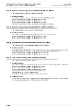
12.4.2 Sending wait flag [M8371, M8401 and M8421]
These devices remain ON while the PLC is waiting to send.
1. Detailed contents
M8371 remains ON while the PLC is waiting to send in communication using communication port ch0.
M8401 remains ON while the PLC is waiting to send in communication using communication port ch1.
M8421 remains ON while the PLC is waiting to send in communication using communication port ch2.
• In full-duplex communication
While the control line is set to the standard or interlink mode in the communication parameter, when the
control line DR (DSR) turns OFF while sending data, the PLC waits to send and M8401 or M8421 turns
ON.
• In half-duplex communication
When the sending request device is set to ON while data is being received, the PLC waits to send and
M8401 or M8421 turns ON.
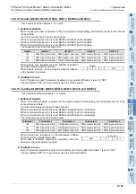
12.4.3 Sending request [M8372, M8402 and M8422]
When these devices are set to ON by SET instruction, the PLC starts to send.
1. Detailed contents
When these devices are set to ON by SET instruction, the PLC starts to send. When sending is completed,
these devices are automatically set to OFF.
When communication port ch0 is used, M8372 is set.
When communication port ch1 is used, M8402 is set.
When communication port ch2 is used, M8422 is set.
2. Cautions on use
When setting these devices to ON, set the drive condition in the pulse type.
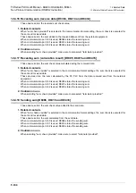
12.4.4 Receiving complete flag [M8373, M8403 and M8423]
These devices turn ON when receiving is completed.
1. Detailed contents
These devices turn ON when receiving is completed.
When communication port ch0 is used, M8373 is set.
When communication port ch1 is used, M8403 is set.
When communication port ch2 is used, M8423 is set.
Receiving is completed in one of the following three conditions.
• When the PLC receives the amount of receive data specified by the RS2 instruction
• When the terminators are set, and the PLC receives the code set by the terminator
• When data receiving is suspended and the PLC does not receive the next set of data within the time set by
the time-out time setting device
When the receiving complete flag turns ON, transfer the received data to another storage destination, and
then set this flag to OFF.
When this flag is set to OFF, the PLC waits to receive.
2. Cautions on use
When the RS2 instruction is driven while the amount of received data is set to "0", the PLC does not wait to
receive. To make the PLC wait to receive it is necessary to set the amount of received data "n" to "1" or more
and set the receiving complete flag to OFF from ON.
Summary of Contents for FX-485ADP
Page 2: ......
Page 120: ...B 2 FX Series PLC User s Manual Data Communication Edition N N Network ...
Page 188: ...C 2 FX Series PLC User s Manual Data Communication Edition Parallel Link ...
Page 244: ...D 2 FX Series PLC User s Manual Data Communication Edition Computer Link ...
Page 344: ...E 2 FX Series PLC User s Manual Data Communication Edition Inverter Communication ...
Page 700: ...H 2 FX Series PLC User s Manual Data Communication Edition Programming Communication ...
Page 752: ...I 2 FX Series PLC User s Manual Data Communication Edition Remote Maintenance ...
Page 817: ......


