G-13
FX Series PLC User's Manual - Data Communication Edition
Non-Protocol Communication (FX
2N
-232IF)
4 Wiring
4.3 Connection to External Equipment with Terminal Specifications (with Control Line)
A
Comm
on I
te
ms
B
N:
N N
etwo
rk
C
Paral
le
l Li
nk
D
Com
puter Li
nk
E
In
verter
C
omm
uni
cation
F
N
on-Proto
col
C
ommunicati
on
(R
S/RS
2 Instru
ction
)
G
No
n-
Protoc
ol
Co
mmuni
ca
tion
(FX
2N
-2
32IF)
H
Programm
ing
Comm
uni
cation
I
Re
mo
te
Ma
intenance
Apx.A
D
isco
nti
nued
models
4.3
Connection to External Equipment with Terminal Specifications
(with Control Line)
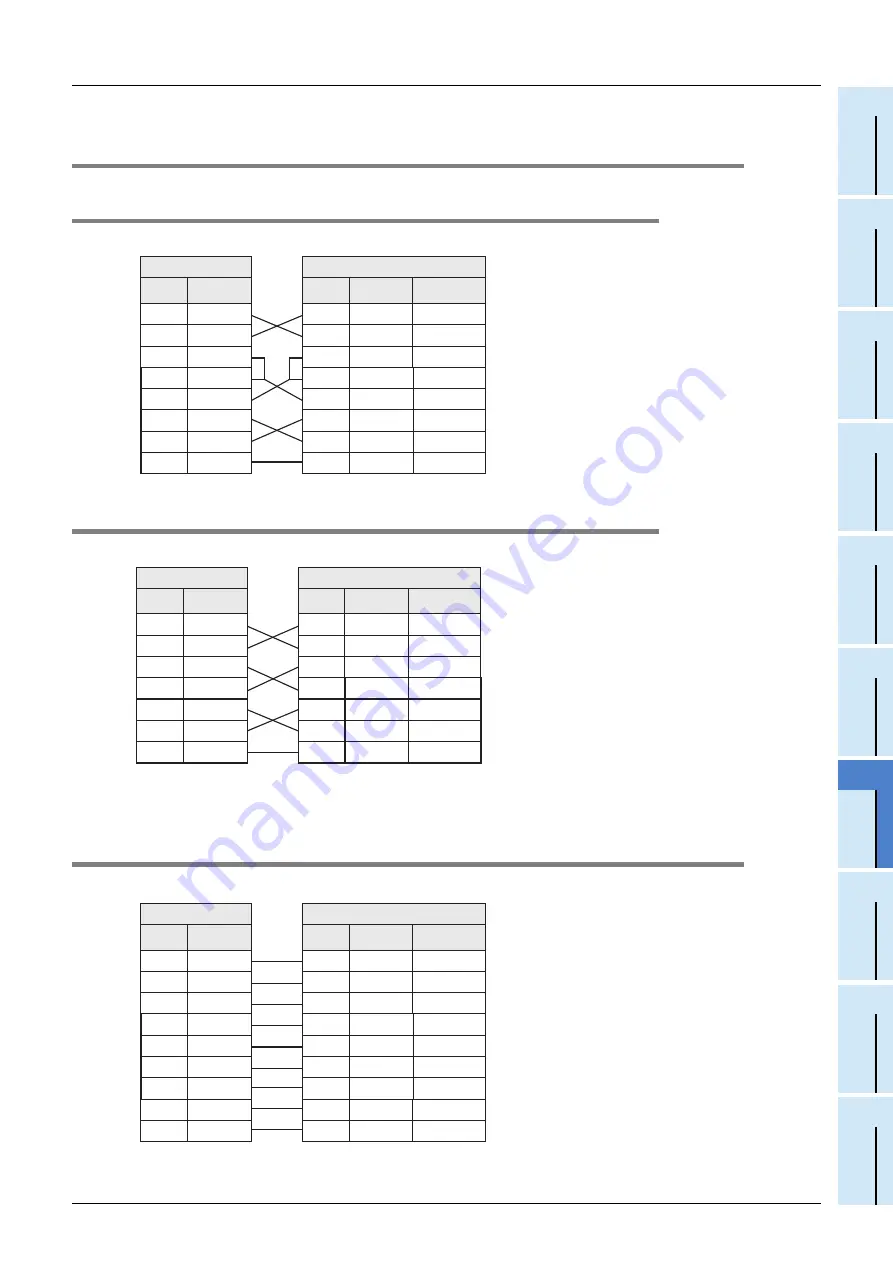
4.3.1
Standard RS-232C mode
Cross cable, BFM #0 (communication format): b9 = 0, b8 = 1 (standard RS-232C mode)
4.3.2
Interlink connection mode
Interlink serial cross cable, BFM #0 (communication format): b9 = 1, b8 = 1 (RS-232C interlink connection mode)
4.4
Connection to External Equipment with Modem Specifications
Straight cable, BFM #0 (communication format): b9 = 0, b8 = 1 (standard RS-232C mode)
PLC side
RS-232C external equipment side
Name
FX
2N
-232IF
Name
9-pin D-Sub 25-pin D-Sub
SD(TXD)
3
SD(TXD)
3
2
RD(RXD)
2
RD(RXD)
2
3
RS(RTS)
7
RS(RTS)
7
4
CS(CTS)
8
CS(CTS)
8
5
CD(DCD)
1
CD(DCD)
1
8
ER(DTR)
4
ER(DTR)
4
20
DR(DSR)
6
DR(DSR)
6
6
SG(GND)
5
SG(GND)
5
7
*1
*1
*2
*2
When the FX
2N
-232IF receives the RS (request
to send) signal at its carrier to send (CS) pin, the
FX
2N
-232IF transfers signals as if the external
equipment exists.
*1. It is not necessary to connect the CD signal if
monitoring the CD signal is not required.
For the CD signal, the 232IF indicates only the
status.
*2. The 232IF indicates only the status.
PLC side
RS-232C external equipment side
Name
Name
9-pin D-Sub 25-pin D-Sub
SD(TXD)
3
SD(TXD)
3
2
RD(RXD)
2
RD(RXD)
2
3
RS(RTS)
7
RS(RTS)
7
4
CS(CTS)
8
CS(CTS)
8
5
ER(DTR)
4
ER(DTR)
4
20
DR(DSR)
6
DR(DSR)
6
6
SG(GND)
5
SG(GND)
5
7
*1
*1
*2
*2
FX
2N
-232IF
In the interlink connection mode, the 232IF can
receive data larger than 512 bytes which is the
upper limit of the received data buffer in the
232IF.
*1. In this mode, the request to send (RS) signal works
as the receiving enable signal for the 232IF.
When the 232IF receives data beyond the
maximum number of receivable bytes, it turns OFF
which works as the receive ready signal (RS signal)
to ask the external equipment to stop sending. At
this time, by withdrawing the data located in the
received data buffer using a sequence program,
the 232IF can receive remaining data.
*2. The 232IF indicates only the status.
PLC side
RS-232C external equipment side
Name
Name
9-pin D-Sub 25-pin D-Sub
SD(TXD)
3
SD(TXD)
3
2
RD(RXD)
2
RD(RXD)
2
3
RS(RTS)
7
RS(RTS)
7
4
CS(CTS)
8
CS(CTS)
8
5
CD(DCD)
1
CD(DCD)
1
8
ER(DTR)
4
ER(DTR)
4
20
DR(DSR)
6
DR(DSR)
6
6
SG(GND)
5
SG(GND)
5
7
CI(RI)
9
CI(RI)
9
22
*3
*3
*2
*2
*1
*1
FX
2N
-232IF
*1. It is not necessary to connect the CD signal if
monitoring the CD signal is not required.
For the CD signal, the 232IF indicates only the
status.
*2. The 232IF indicates only the status.
*3. It is not necessary to connect the CI signal if
monitoring of the CI signal is not required. For the
CI signal, the 232IF indicates only the status.
Summary of Contents for FX-485ADP
Page 2: ......
Page 120: ...B 2 FX Series PLC User s Manual Data Communication Edition N N Network ...
Page 188: ...C 2 FX Series PLC User s Manual Data Communication Edition Parallel Link ...
Page 244: ...D 2 FX Series PLC User s Manual Data Communication Edition Computer Link ...
Page 344: ...E 2 FX Series PLC User s Manual Data Communication Edition Inverter Communication ...
Page 700: ...H 2 FX Series PLC User s Manual Data Communication Edition Programming Communication ...
Page 752: ...I 2 FX Series PLC User s Manual Data Communication Edition Remote Maintenance ...
Page 817: ......


