G-28
FX Series PLC User's Manual - Data Communication Edition
Non-Protocol Communication (FX
2N
-232IF)
5 Creating Programs
5.4 Buffer Memory (BFM)
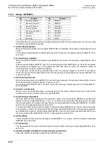
5.4.17 Status <BFM #28>
This buffer stores the 232IF status and sending/receiving result as the status information. The PLC can read
this buffer using the FROM instruction.
1. b0 (sending complete)
When sending the specified amount of bytes (BFM #1000) is completed, the sending complete flag (b0) is set
to ON.
The sending complete flag (b0) is automatically set to OFF when the next sending command (BFM #1, b1) is
set to ON.
2. b1 (receiving complete)
When the maximum number of receivable bytes (BFM #2) are received, the receiving complete flag (b1) is set
to ON.
If the receiving terminator (BFM #11 and 10) or receiving timeout time (BFM #3) is set, the 232IF recognizes
that receiving is completed even if the already received data does not reach the maximum number of
received bytes when either condition is satisfied.
It is necessary to set this receiving complete flag to OFF in a sequence program. The 232IF is not ready to
receive the next set of data while this bit is ON. Use the receiving complete flag reset command (BFM #1, b2)
to set this bit to OFF.
3. b2 (receiving timeout)
When the receiving timeout time (BFM #3) is reached during receiving, the receiving timeout bit (b2) is set to
ON. And the receiving complete flag (b1) is also set to ON.
The receiving timeout status (b2) is set to OFF when the receiving complete flag reset command (BFM #1,
b2) is executed.
4. b3 (error occurrence)
When an error occurs during sending or receiving, the error occurrence status bit (b3) is set to ON and the
contents of the error are stored in the error code (BFM #29).
5. b4 (receiving suspended)
When the 232IF receives data beyond the maximum number of receivable bytes (BFM #2) in the RS-232C
interlink connection mode (BFM #0, b9 = 1, b8 = 1), it sets the receiving enable (RS) signal to OFF and asks
the external equipment to suspend sending. After the receiving suspension waiting time (BFM #12), the 232IF
sets the receiving suspended status bit (b4) to ON.
To receive data beyond the maximum number of receivable bytes (BFM #2) in the interlink connection mode,
it is necessary to monitor the rising edge of this receiving suspended status bit (b4) in the sequence program,
and withdraw the number of received bytes (BFM #2000) or amount of received data buffers (BFM #14) from
the received data buffer (BFM #2001 to 2271) to data registers inside the PLC.
6. b6 (sending)
This bit remains ON from when the sending command (BFM #1, b1) is given until the sending complete flag
(BFM #28, b0) is set to ON.
7. b7 (receiving)
This bit remains ON from when the head data is received until the receiving complete flag (BFM #28, b1) is
set to ON.
8. b8 (RS), b9 (ER), b12 (DR), b13 (CD), b14 (CS) and b15 (CI)
These bits indicate the operation status by their ON/OFF status.
Bit
Contents
Bit
Contents
b0
Sending complete
b8
RS(RTS)
b1
Receiving complete
b9
ER(DTR)
b2
Receiving timeout
b10
Undefined
b3
Error occurrence
b11
Undefined
b4
Receiving suspended
b12
DR(DSR)
b5
Undefined
b13
CD(DCD)
b6
Sending
b14
DS(CTS)
b7
Receiving
b15
CI(RI)
Summary of Contents for FX-485ADP
Page 2: ......
Page 120: ...B 2 FX Series PLC User s Manual Data Communication Edition N N Network ...
Page 188: ...C 2 FX Series PLC User s Manual Data Communication Edition Parallel Link ...
Page 244: ...D 2 FX Series PLC User s Manual Data Communication Edition Computer Link ...
Page 344: ...E 2 FX Series PLC User s Manual Data Communication Edition Inverter Communication ...
Page 700: ...H 2 FX Series PLC User s Manual Data Communication Edition Programming Communication ...
Page 752: ...I 2 FX Series PLC User s Manual Data Communication Edition Remote Maintenance ...
Page 817: ......

