H-11
FX Series PLC User's Manual - Data Communication Edition
Programming Communication
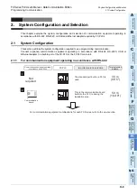
2 System Configuration and Selection
2.1 System Configuration
A
Comm
on I
te
ms
B
N:
N N
etwo
rk
C
Paral
le
l Li
nk
D
Com
puter Li
nk
E
In
verter
C
omm
uni
cation
F
N
on-Proto
col
C
ommunicati
on
(R
S/RS
2 Instru
ction
)
G
No
n-
Protoc
ol
Co
mmuni
ca
tion
(FX
2N
-2
32IF)
H
Programm
ing
Comm
uni
cation
I
Re
mo
te
Ma
intenance
Apx.A
D
isco
nti
nued
models
2.1.4
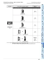
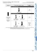
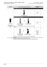
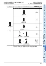
For Ethernet adapter
*1.
Indicates the distance between the hub and a node.
The maximum distance varies depending on the Ethernet equipment used.
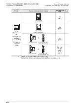
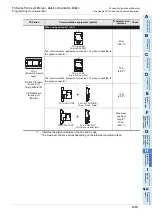
, and indicate the communication equipment combination patterns.
1
2
3
Attach the connector conversion adapter
to the main unit, and then attach the
FX
3U
-ENET-ADP to the left side
of the main unit.
FX
3U
-ENET-ADP
FX PLC
+
+
FX
3U
-ENET-ADP
FX
3U
-ENET-ADP
FX
3U
-ENET-ADP
+
+
Connector
conversion board
Important point in selection
Attach the connector conversion
board to the main unit, and then
attach the FX
3U
-ENET-ADP to
the left side of the main unit.
Maximum
segment length
*1
100 m
(380' 1")
100 m
(380' 1")
100 m
(380' 1")
1
+
Attach the FX
3U
-ENET-ADP to
the left side of the main unit.
3
2
For communication equipment combinations for each FX Series, refer to the next section.
Connector
conversion adapter
Summary of Contents for FX-485ADP
Page 2: ......
Page 120: ...B 2 FX Series PLC User s Manual Data Communication Edition N N Network ...
Page 188: ...C 2 FX Series PLC User s Manual Data Communication Edition Parallel Link ...
Page 244: ...D 2 FX Series PLC User s Manual Data Communication Edition Computer Link ...
Page 344: ...E 2 FX Series PLC User s Manual Data Communication Edition Inverter Communication ...
Page 700: ...H 2 FX Series PLC User s Manual Data Communication Edition Programming Communication ...
Page 752: ...I 2 FX Series PLC User s Manual Data Communication Edition Remote Maintenance ...
Page 817: ......

