I-25
FX Series PLC User's Manual - Data Communication Edition
Remote Maintenance
5 How to Setup Modems on the PLC Side
5.1 Setting Using GX Works2
A
Comm
on I
te
ms
B
N:
N N
etwo
rk
C
Paral
le
l Li
nk
D
Com
puter Li
nk
E
In
verter
C
omm
uni
cation
F
N
on-Proto
col
C
ommunicati
on
(R
S/RS
2 Instru
ction
)
G
No
n-
Protoc
ol
Co
mmuni
ca
tion
(FX
2N
-2
32IF)
H
Programm
ing
Comm
uni
cation
I
Re
mo
te
Ma
intenance
Apx.A
D
isco
nti
nued
models
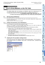
5. How to Setup Modems on the PLC Side
This chapter explains how to set parameters for initialization using the AT command and set the
communication specifications including the transmission speed for a modem connected to the PLC.
The setting method using GX Works2 and the setting method using FXGP/WIN are explained.
For applicable programming tools, refer to Subsection 1.4.2.
For details on GX Developer operating procedure, refer to GX Developer Operating Manual.
5.1
Setting Using GX Works2
This section explains the modem initialization setting and communication setting methods. Suppose that GX
Works2 is already started up.
Screens for the FX
3U
PLC are shown as examples.
5.1.1
Setting communication by way of RS-232C port
It is not necessary to set the serial communication with a modem.
However, it is necessary to verify that another communication type is not used and whether the
communication setting is correct using the following procedure.
In FX PLCs, the communication setting can be executed using either of the following two methods:
1) Writing the value "0" to the data register D8120 using a sequence program
If another communication type is already set for another application, delete the sequence program which
writes a value to D8120.
When setting remote maintenance to ch1 in an FX
3S
/FX
3G
/FX
3GC
/FX
3U
/FX
3UC
PLC, write the value "0" to
the data register D8120, D8400.
When setting remote maintenance to ch2 in an FX
3G
/FX
3GC
/FX
3U
/FX
3UC
PLC, write the value "0" to the
data register D8420.
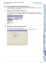
2) Setting parameters using a sequence programming tool
By using the following procedure, verify that another communication type is not set.
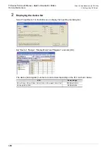
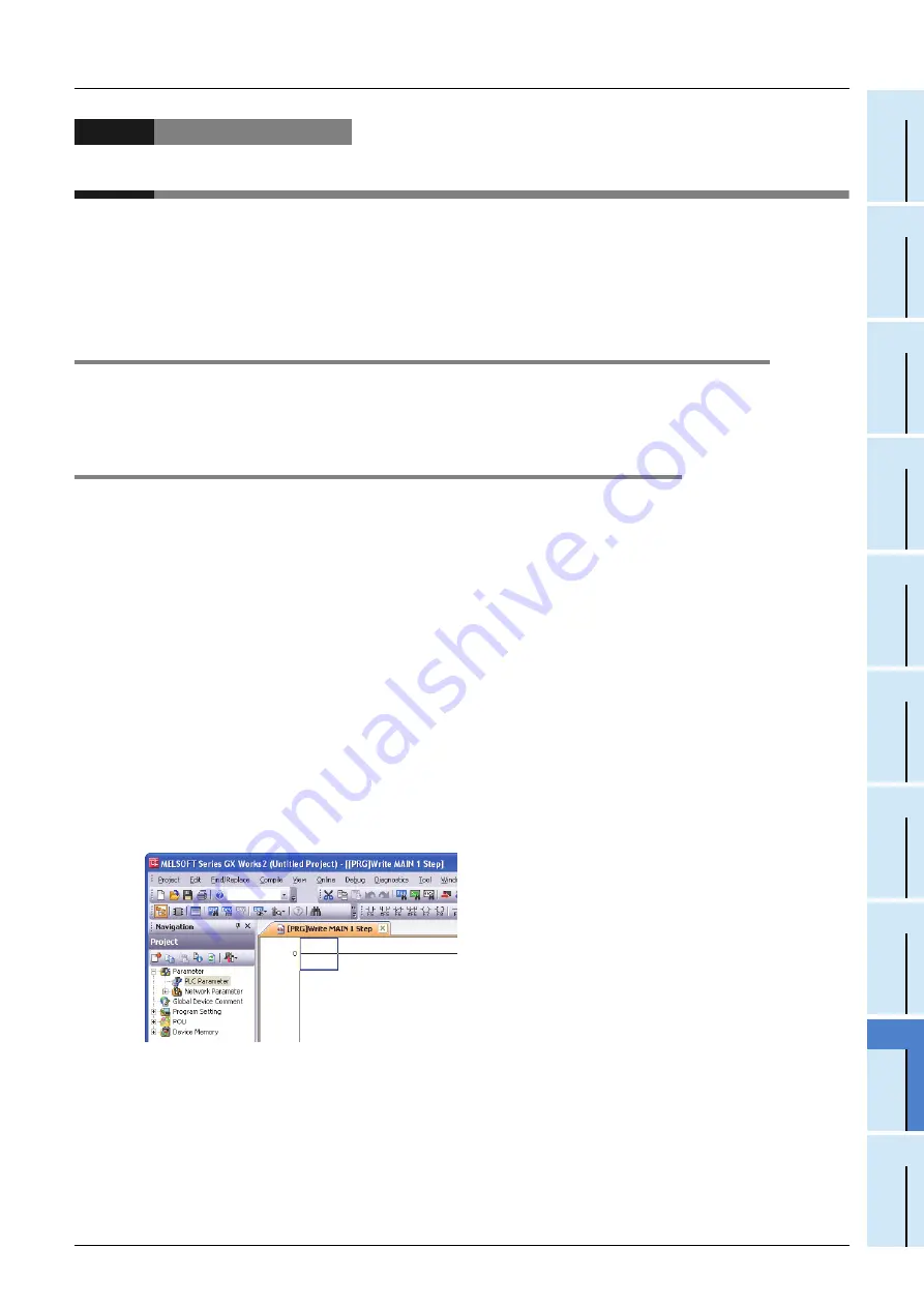
1
Opening the PLC parameter setting window
In the project view area of the navigation window, double-click [Parameter]
[PLC Parameter].
If the navigation window is not displayed, select [View]
[Docking Window]
[Navigation] from
the menu bar.
Summary of Contents for FX-485ADP
Page 2: ......
Page 120: ...B 2 FX Series PLC User s Manual Data Communication Edition N N Network ...
Page 188: ...C 2 FX Series PLC User s Manual Data Communication Edition Parallel Link ...
Page 244: ...D 2 FX Series PLC User s Manual Data Communication Edition Computer Link ...
Page 344: ...E 2 FX Series PLC User s Manual Data Communication Edition Inverter Communication ...
Page 700: ...H 2 FX Series PLC User s Manual Data Communication Edition Programming Communication ...
Page 752: ...I 2 FX Series PLC User s Manual Data Communication Edition Remote Maintenance ...
Page 817: ......

