B-63
FX Series PLC User's Manual - Data Communication Edition
N:N Network
10 Related Data
10.2 Details of Related Devices
A
Comm
on I
te
ms
B
N:
N N
etwo
rk
C
Paral
le
l Li
nk
D
Com
puter Li
nk
E
In
verter
C
omm
uni
cation
F
N
on-Proto
col
C
ommunicati
on
(R
S/RS
2 Instru
ction
)
G
No
n-
Protoc
ol
Co
mmuni
ca
tion
(FX
2N
-2
32IF)
H
Programm
ing
Comm
uni
cation
I
Re
mo
te
Ma
intenance
Apx.A
D
isco
nti
nued
models
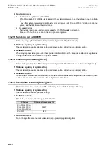
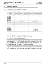
10.2.11 Slave station quantity setting [D8177]
Set a value ranging from 1 to 7 to the special data register D8177 (initial value: 7).
1. Stations requiring program setting
The master station requires program setting, and slave stations do not require program setting.
2. Detailed contents
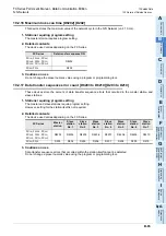
10.2.12 Refresh range setting [D8178]
Set a value ranging from 0 to 2 to the special data register D8178 (initial value: 0).
1. Stations requiring program setting
The master station requires program setting, and slave stations do not require program setting.
2. Pattern applicability in FX PLC
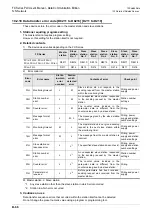
3. Number and assignment of link devices
The number of link devices varies depending on the selected pattern, but the head device number remains
the same.
It is recommended to leave unused numbers in the unused status to enable pattern change in the future.
Set value
Description
Set value
Description
0
Not applicable
4
Four slave stations are connected.
1
One slave station is connected.
5
Five slave stations are connected.
2
Two slave stations are connected.
6
Six slave stations are connected.
3
Three slave stations are connected.
7
Seven slave stations are connected.
FX Series
Pattern (set value)
Pattern 0 (0)
Pattern 1 (1)
Pattern 2 (2)
FX
0N
PLC
Not applicable
Not applicable
FX
1S
PLC
Not applicable
Not applicable
FX
1N
, FX
1NC
PLC
FX
2N
, FX
2NC
PLC
FX
3S
PLC
FX
3G
, FX
3GC
PLC
FX
3U
, FX
3UC
PLC
Station
No.
Pattern 0
Pattern 1
Pattern 2
Bit device
(M)
Word device
(D)
Bit device
(M)
Word device
(D)
Bit device
(M)
Word device
(D)
0
4 in each
station
32 in each
station
4 in each
station
64 in each
station
8 in each
station
0
—
D 0 to D 3
M1000 to M1031
D 0 to D 3
M1000 to M1063
D 0 to D 7
1
—
D10 to D13
M1064 to M1095
D10 to D13
M1064 to M1127
D10 to D17
2
—
D20 to D23
M1128 to M1159
D20 to D23
M1128 to M1191
D20 to D27
3
—
D30 to D33
M1192 to M1223
D30 to D33
M1192 to M1255
D30 to D37
4
—
D40 to D43
M1256 to M1287
D40 to D43
M1256 to M1319
D40 to D47
5
—
D50 to D53
M1320 to M1351
D50 to D53
M1320 to M1383
D50 to D57
6
—
D60 to D63
M1384 to M1415
D60 to D63
M1384 to M1447
D60 to D67
7
—
D70 to D73
M1448 to M1479
D70 to D73
M1448 to M1511
D70 to D77
Summary of Contents for FX-485ADP
Page 2: ......
Page 120: ...B 2 FX Series PLC User s Manual Data Communication Edition N N Network ...
Page 188: ...C 2 FX Series PLC User s Manual Data Communication Edition Parallel Link ...
Page 244: ...D 2 FX Series PLC User s Manual Data Communication Edition Computer Link ...
Page 344: ...E 2 FX Series PLC User s Manual Data Communication Edition Inverter Communication ...
Page 700: ...H 2 FX Series PLC User s Manual Data Communication Edition Programming Communication ...
Page 752: ...I 2 FX Series PLC User s Manual Data Communication Edition Remote Maintenance ...
Page 817: ......

