C-52
FX Series PLC User's Manual - Data Communication Edition
Parallel Link
10 Related Data
10.1 Related Device List
10. Related Data
10.1
Related Device List
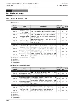
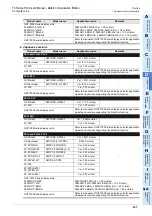
1. Bit devices
R: Read only (used as a contact in program)
W: Write only
M: Master station
L: Slave station
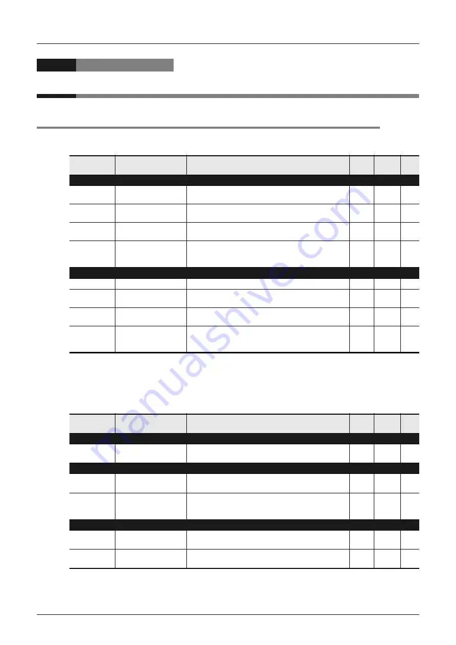
2. Word devices (data registers)
R: Read only
W: Write only
M: Master station
L: Slave station
Device
number
Name
Description
Initial
value
Detec-
tion
R/W
Devices for communication setting
M8070
Parallel link master
station setting
Links a PLC as the master station when it turns ON.
M
W
M8071
Parallel link slave
station setting
Links a PLC as the slave station when it turns ON.
L
W
M8162
High speed parallel
link mode
Turns ON when two-word device communication
mode is selected.
M, L
W
M8178
Channel setting
Sets the communication port to be used. (in the FX
3G
,
FX
3GC
,
FX
3U
and FX
3UC
)
OFF: ch1, ON: ch2
M, L
W
Devices for checking communication status
M8072
Parallel link ON
Remains ON while the parallel link is being executed.
M, L
R
M8073
Parallel link setting
error
Turns ON when an error is included in the setting
contents of the master station or slave station.
M, L
R
M8063
Serial communication
error 1 (ch 1)
Turns ON when an error occurs in serial
communication using ch 1.
M, L
R
M8438
Serial communication
error 2 (ch 2)
Turns ON when an error occurs in serial
communication using ch 2. (in the FX
3G
, FX
3GC
,
FX
3U
and FX
3UC
)
M, L
R
Device
number
Name
Description
Initial
value
Detec-
tion
R/W
Devices for communication setting
D8070
Error judgement time
Sets the error judgement time for data
communication in the parallel link.
500
M, L
W
Devices for checking communication status
D8063
Serial communication
error code 1 (ch 1)
Stores the error code when an error occurs in serial
communication using ch 1.
0000
M, L
R
D8438
Serial communication
error code 2 (ch 2)
Stores the error code when an error occurs in serial
communication using ch 2. (in the FX
3G
, FX
3GC
,
FX
3U
and FX
3UC
)
0000
M, L
R
Devices for checking
D8419
Operation mode
display (ch 1)
Stores the communication type being used by
ch 1. (in the FX
3S
, FX
3G
, FX
3GC
,
FX
3U
and FX
3UC
)
—
M, L
R
D8439
Operation mode
display (ch 2)
Stores the communication type being used by
ch 2. (in the FX
3G
, FX
3GC
,
FX
3U
and FX
3UC
)
—
M, L
R
Summary of Contents for FX-485ADP
Page 2: ......
Page 120: ...B 2 FX Series PLC User s Manual Data Communication Edition N N Network ...
Page 188: ...C 2 FX Series PLC User s Manual Data Communication Edition Parallel Link ...
Page 244: ...D 2 FX Series PLC User s Manual Data Communication Edition Computer Link ...
Page 344: ...E 2 FX Series PLC User s Manual Data Communication Edition Inverter Communication ...
Page 700: ...H 2 FX Series PLC User s Manual Data Communication Edition Programming Communication ...
Page 752: ...I 2 FX Series PLC User s Manual Data Communication Edition Remote Maintenance ...
Page 817: ......


