D-27
FX Series PLC User's Manual - Data Communication Edition
Computer Link
4 Wiring
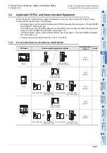
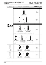
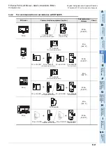
3.2 Applicable FX PLC and Communication Equipment
A
Comm
on I
te
ms
B
N:
N N
etwo
rk
C
Paral
le
l Li
nk
D
Com
puter Li
nk
E
In
verter
C
omm
uni
cation
F
N
on-Proto
col
C
ommunicati
on
(R
S/RS
2 Instru
ction
)
G
No
n-
Protoc
ol
Co
mmuni
ca
tion
(FX
2N
-2
32IF)
H
Programm
ing
Comm
uni
cation
I
Re
mo
te
Ma
intenance
Apx.A
D
isco
nti
nued
models
4. Wiring
This chapter explains the wiring.
WIRING PRECAUTIONS
• Make sure to cut off all phases of the power supply externally before attempting installation or wiring work.
Failure to do so may cause electric shock or damage to the product.
• Make sure to attach the terminal cover, offered as an accessory, before turning on the power or initiating
operation after installation or wiring work.
Failure to do so may cause electric shock.
WIRING PRECAUTIONS
• Make sure to observe the following precautions in order to prevent any damage to the machinery or accidents
due to abnormal data written to the PLC under the influence of noise:
1) Do not bundle the main circuit line together with or lay it close to the main circuit, high-voltage line or load line.
Otherwise, noise disturbance and/or surge induction are likely to take place. As a guideline, lay the control line
at least 100mm (3.94") or more away from the main circuit or high-voltage lines.
2) Ground the shield wire or shield of the shielded cable at one point on the PLC. However, do not use common
grounding with heavy electrical systems.
• Make sure to properly wire the terminal block in accordance with the following precautions.
Failure to do so may cause electric shock, equipment failures, a short-circuit, wire breakage, malfunctions, or
damage to the product.
- The disposal size of the cable end should follow the dimensions described in the manual.
- Tightening torque should follow the specifications in the manual.
- Tighten the screws using a Phillips-head screwdriver No.2 (shaft diameter 6mm (0.24") or less). Make sure
that the screwdriver does not touch the partition part of the terminal block.
• Make sure to properly wire to the terminal block (European type) in accordance with the following precautions.
Failure to do so may cause electric shock, equipment failures, a short-circuit, wire breakage, malfunctions, or
damage to the product.
- The disposal size of the cable end should follow the dimensions described in the manual.
- Tightening torque should follow the specifications in the manual.
- Twist the end of strand wire and make sure that there are no loose wires.
- Do not solder-plate the electric wire ends.
- Do not connect more than the specified number of wires or electric wires of unspecified size.
- Affix the electric wires so that neither the terminal block nor the connected parts are directly stressed.
Summary of Contents for FX-485ADP
Page 2: ......
Page 120: ...B 2 FX Series PLC User s Manual Data Communication Edition N N Network ...
Page 188: ...C 2 FX Series PLC User s Manual Data Communication Edition Parallel Link ...
Page 244: ...D 2 FX Series PLC User s Manual Data Communication Edition Computer Link ...
Page 344: ...E 2 FX Series PLC User s Manual Data Communication Edition Inverter Communication ...
Page 700: ...H 2 FX Series PLC User s Manual Data Communication Edition Programming Communication ...
Page 752: ...I 2 FX Series PLC User s Manual Data Communication Edition Remote Maintenance ...
Page 817: ......

