D-47
FX Series PLC User's Manual - Data Communication Edition
Computer Link
6 Control Procedures and Setting Methods
6.3 How to Understand Control Procedure
A
Comm
on I
te
ms
B
N:
N N
etwo
rk
C
Paral
le
l Li
nk
D
Com
puter Li
nk
E
In
verter
C
omm
uni
cation
F
N
on-Proto
col
C
ommunicati
on
(R
S/RS
2 Instru
ction
)
G
No
n-
Protoc
ol
Co
mmuni
ca
tion
(FX
2N
-2
32IF)
H
Programm
ing
Comm
uni
cation
I
Re
mo
te
Ma
intenance
Apx.A
D
isco
nti
nued
models
6.3
How to Understand Control Procedure
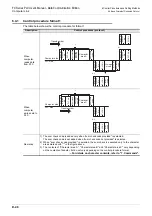
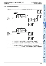
This section explains how to understand the transfer data shown in the later description of each function.
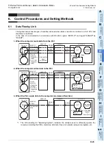
1. When the computer reads data from the PLC (computer
PLC)
[1] Parts A and C indicate transfer from the computer to the PLC.
[2] Part B indicates transfer from the PLC to the computer.
[3] Create a program in the computer so that each data is transferred in turn from the left to the right, and
that the data is transferred in the order "A
B
C" as a whole.
(Example: In the part A, data is transferred in turn from the right starting from "ENQ".)
2. When the computer writes data to the PLC (computer
PLC)
[1] Part A indicates transfer from the computer to the PLC.
[2] Part B indicates transfer from the PLC to the computer.
[3] Create a program in the computer so that each data is transferred in turn from the left to the right, and
that the data is transferred in the order "A
B" as a whole.
(Example: In the part A, data is transferred in turn from the right starting from "ENQ".)
6.4
Basic Formats of Dedicated Protocol
There are two types of control procedures in dedicated protocols.
CR and LF are not added to each block in format 1. CR and LF are added to each block in format 4.
(The format names are the same as those used in the computer link units for A Series PLCs.)
This section explains the contents of control procedures and the contents of each item specified in the control
procedures in each format.
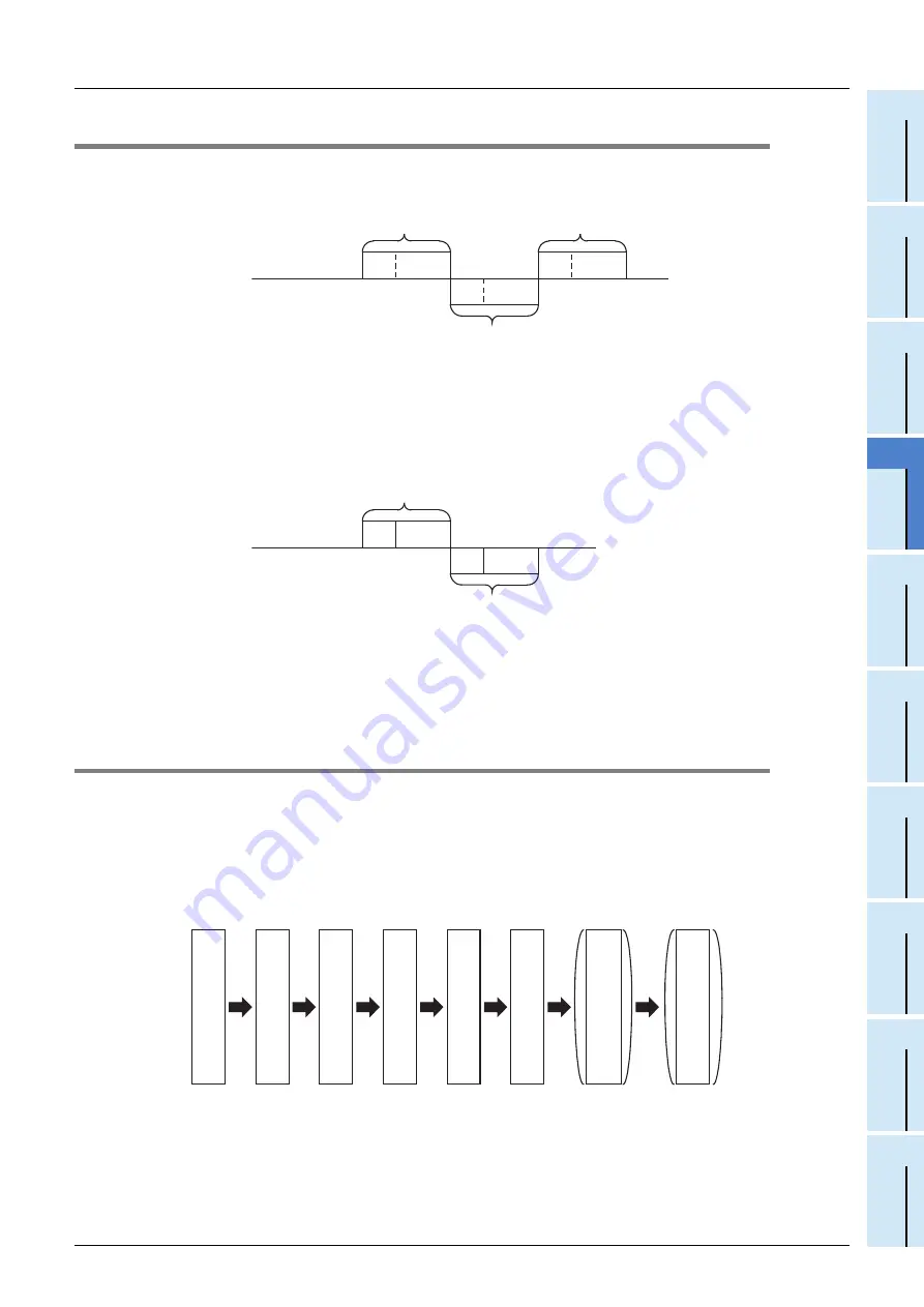
The basic format of control procedures (protocols) is as shown below:
For details, refer to Subsections 6.4.1 and 6.4.2.
*1.
Whether or not the sum check code is added can be specified using a parameter.
*2.
Whether or not the control code is added can be specified by selecting the protocol type.
Computer side
PLC side
Data
S
T
X
Data
A
C
K
Data
A
C
B
E
N
Q
Computer side
PLC side
Data
Data
A
C
K
A
B
E
N
Q
C
o
ntrol code
M
e
ssage w
a
iting tim
e
C
om
m
and
P
LC
num
ber
S
tation num
ber
S
um
check code
C
h
aracter
C
o
ntrol code C
R
LF
*1
*2
Summary of Contents for FX-485ADP
Page 2: ......
Page 120: ...B 2 FX Series PLC User s Manual Data Communication Edition N N Network ...
Page 188: ...C 2 FX Series PLC User s Manual Data Communication Edition Parallel Link ...
Page 244: ...D 2 FX Series PLC User s Manual Data Communication Edition Computer Link ...
Page 344: ...E 2 FX Series PLC User s Manual Data Communication Edition Inverter Communication ...
Page 700: ...H 2 FX Series PLC User s Manual Data Communication Edition Programming Communication ...
Page 752: ...I 2 FX Series PLC User s Manual Data Communication Edition Remote Maintenance ...
Page 817: ......

