D-56
FX Series PLC User's Manual - Data Communication Edition
Computer Link
6 Control Procedures and Setting Methods
6.6 Transfer Data in Character Area
6.6
Transfer Data in Character Area
This section explains the transfer data in the character area sent and received between the computer and a
PLC using each command.
The transfer data explained below is handled as the character area B in reading and the character area C in
writing.
For character areas, refer to Subsections 6.4.1 and 6.4.2.
6.6.1
When bit device memory is read or written
The bit device memory is handled in 1-bit (1-point)
units
or in 1-word (16-point)
units
.
The transfer data in each case is explained below.
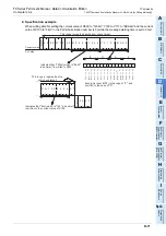
1) In 1-bit (1-point)
units
When the bit device memory is handled in 1-bit (1-point) units, a specified number of devices starting
from the specified head device are expressed in turn from the left end in "1 (31H)" for the ON status or "0
(30H)" for the OFF status.
Example: When indicating the ON/OFF status of five devices starting from M10
2) In 1-word (16-point)" units
When the bit device memory is handled in 1-word (16-point) units, one word is expressed in 4-bit units in
turn from the most significant bit in hexadecimal.
Example: When indicating the ON/OFF status of 32 devices starting from M16
4D
H
30
H
31
H
30
H
30
H
35
H
30
H
Head device
M 0 0 1 0
Number
of
devices
0 5
1 0 1 0 1
31
H
31
H
30
H
31
H
30
H
Indicates that M14 is ON.
Indicates that M12 is ON.
Indicates that M13 is OFF.
Indicates that M10 is ON.
Indicates that M11 is OFF.
4D
H
36
H
31
H
30
H
30
H
32
H
30
H
Head device
M 0 0 1 6
Number
of
devices
0 2
Data
A B 1 2
41
H
32
H
31
H
42
H
Data
3 4 C D
33
H
44
H
43
H
34
H
Because devices are handled in 16 point units,
the number of device is "02".
1 0 1
0
0
0
0
0
0
0
0
0
0
1
1
1
1
1
1
1
1
1
1
1
1
1
0 0
0
0
0
0
b15
b11
b12
b13
b14
b9
b10
b8
b5
b6
b7
b4
b1
b2
b3
b15
b11
b12
b13
b14
b9
b10
b8
b5
b6
b7
b4
b1
b2
b3
b0
b0
M
31
M
17
M
18
M
19
M
20
M
21
M
22
M
23
M
24
M
25
M
26
M
27
M
28
M
29
M
30
M
35
M
36
M
38
M
37
M
39
M
40
M
41
M
42
M
43
M
44
M
45
M
46
M
47
M
16
M
33
M
34
M
32
A
B
D
C
4
3
2
1
Summary of Contents for FX-485ADP
Page 2: ......
Page 120: ...B 2 FX Series PLC User s Manual Data Communication Edition N N Network ...
Page 188: ...C 2 FX Series PLC User s Manual Data Communication Edition Parallel Link ...
Page 244: ...D 2 FX Series PLC User s Manual Data Communication Edition Computer Link ...
Page 344: ...E 2 FX Series PLC User s Manual Data Communication Edition Inverter Communication ...
Page 700: ...H 2 FX Series PLC User s Manual Data Communication Edition Programming Communication ...
Page 752: ...I 2 FX Series PLC User s Manual Data Communication Edition Remote Maintenance ...
Page 817: ......

