E-125
FX Series PLC User's Manual - Data Communication Edition
Inverter Communication
10 Practical Program Examples (FX3S, FX3G, FX3GC, FX3U, FX3UC)
10.2 Practical Example 2
A
Comm
on I
te
ms
B
N:
N N
etwo
rk
C
Paral
le
l Li
nk
D
Com
puter Li
nk
E
In
verter
C
omm
uni
cation
F
N
on-Proto
col
C
ommunicati
on
(R
S/RS
2 Instru
ction
)
G
No
n-
Protoc
ol
Co
mmuni
ca
tion
(FX
2N
-2
32IF)
H
Programm
ing
Comm
uni
cation
I
Re
mo
te
Ma
intenance
Apx.A
D
isco
nti
nued
models
10.2
Practical Example 2
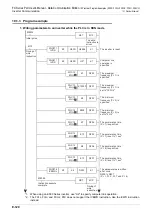
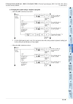
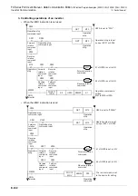
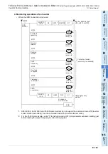
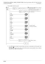
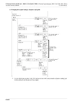
This program executes the same control as practical example 1 shown earlier from one communication port
(ch1) to two inverters (Station number: 0 and 1).
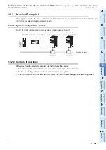
10.2.1 System configuration example
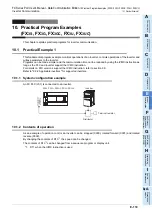
An FX PLC (ch1) is connected to two inverters (Station number: 0 and 1).
10.2.2 Contents of operation
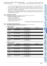
Differences from the practical example 1 are the following three points:
• The PLC executes communication from one communication port to two inverters.
• Status is not being read when a write to inverter command is given.
• The PLC only writes when it detects that contents to be written have changed since last being written.
FX
3S,
FX
3G,
FX
3GC,
FX
3U,
FX
3UC
Terminal resistor
Distributor
Inverter B
(station number 1)
Distributor
Inverter A
(station number 0)
Summary of Contents for FX-485ADP
Page 2: ......
Page 120: ...B 2 FX Series PLC User s Manual Data Communication Edition N N Network ...
Page 188: ...C 2 FX Series PLC User s Manual Data Communication Edition Parallel Link ...
Page 244: ...D 2 FX Series PLC User s Manual Data Communication Edition Computer Link ...
Page 344: ...E 2 FX Series PLC User s Manual Data Communication Edition Inverter Communication ...
Page 700: ...H 2 FX Series PLC User s Manual Data Communication Edition Programming Communication ...
Page 752: ...I 2 FX Series PLC User s Manual Data Communication Edition Remote Maintenance ...
Page 817: ......

