E-144
FX Series PLC User's Manual - Data Communication Edition
Inverter Communication
12 Related Data
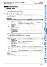
12.3 Related Device List (FX3S, FX3G, FX3GC, FX3U, FX3UC)
12.3
Related Device List (FX
3S
, FX
3G
, FX
3GC
, FX
3U
, FX
3UC
)
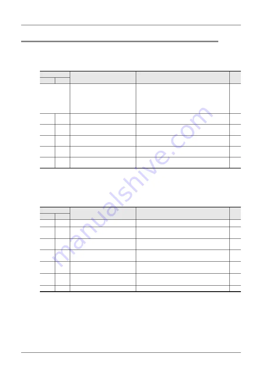
The tables below show special auxiliary relays and special data registers used in inverter communication
(FNC270 (IVCK) to FNC275 (IVMC)).
The FX
3G
PLC (14-point, 24-point type) and FX
3S
PLC does not support ch2.
1. Bit devices
R: Read only (used as a contact in program)
*1.
Cleared when PLC power supply is turned from OFF to ON.
*2.
Cleared when the PLC mode is changed from STOP to RUN.
*3.
The IVBWR instruction is supported only in FX
3U
and FX
3UC
PLCs.
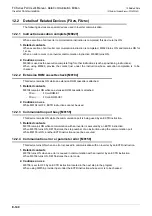
2. Word devices
R: Read only
W: Write only
R/W: Read or Write
*4.
Cleared when PLC power supply is turned from OFF to ON.
*5.
Cleared when the PLC mode is changed from STOP to RUN.
*6.
The IVBWR instruction is supported only in FX
3U
and FX
3UC
PLCs.
*7.
Updated only for the first error occurrence, and not for the second error occurrence or later.
Device No.
Name
Description
R/W
ch1
ch2
M8029
Instruction execution complete
Turns ON when the execution of inverter
communication instruction is completed, and remains
ON for 1 scan.
Turns ON also when the execution of instruction is
completed if inverter communication error flag
(M8152 or M8157) turns ON.
R
M8063 M8438 Serial communication error
*1
Turns ON when an error occurs in any type of
communication.
R
M8151 M8156 Inverter communicating
Remains ON while inverter communication is being
executed.
R
M8152 M8157 Inverter communication error
*2
Turns ON when an error occurs during
communication with an inverter.
R
M8153 M8158 Inverter communication error latch
*2
Turns ON when an error occurs during
communication with an inverter.
R
M8154 M8159 IVBWR instruction error
*2, *3
Turns ON when an error is caused by IVBWR
instruction.
R
Device No.
Name
Description
R/W
ch1
ch2
D8063 D8438 Error code for serial communication
*4
Stores a communication error code.
R
D8150 D8155
Inverter communication response
waiting time
*4
Sets the response wait time of inverter
communication.
R/W
D8151 D8156
Step number of instruction executing
inverter communication
Stores the step number of an instruction executing
inverter communication.
R
D8152 D8157
Error code for inverter
communication
*5
Stores an inverter communication error code.
R
D8153 D8158
Inverter communication error
occurring step latch
*5
Latches a step number in which an inverter
communication error has occurred.
*7
R
D8154 D8159
Error parameter number of IVBWR
instruction
*5*6
Stores a parameter number in which an IVBWR
instruction error has occurred.
R
D8419 D8439 Operation mode display
Stores the communication type being used.
R
Summary of Contents for FX-485ADP
Page 2: ......
Page 120: ...B 2 FX Series PLC User s Manual Data Communication Edition N N Network ...
Page 188: ...C 2 FX Series PLC User s Manual Data Communication Edition Parallel Link ...
Page 244: ...D 2 FX Series PLC User s Manual Data Communication Edition Computer Link ...
Page 344: ...E 2 FX Series PLC User s Manual Data Communication Edition Inverter Communication ...
Page 700: ...H 2 FX Series PLC User s Manual Data Communication Edition Programming Communication ...
Page 752: ...I 2 FX Series PLC User s Manual Data Communication Edition Remote Maintenance ...
Page 817: ......

