E-208
FX Series PLC User's Manual - Data Communication Edition
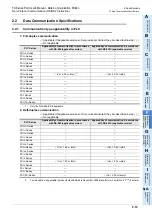
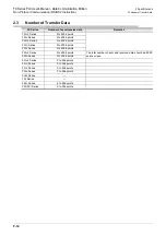
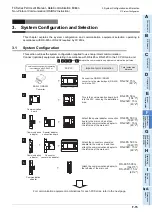
Inverter Communication
12 Related Data
12.5 FREQROL Inverter Parameter List
12.5.4 Communication parameters
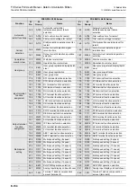
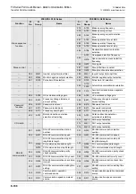
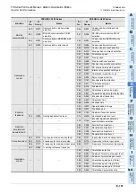
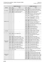
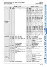
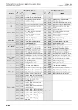
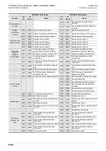
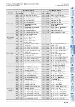
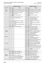
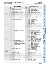
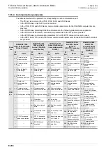
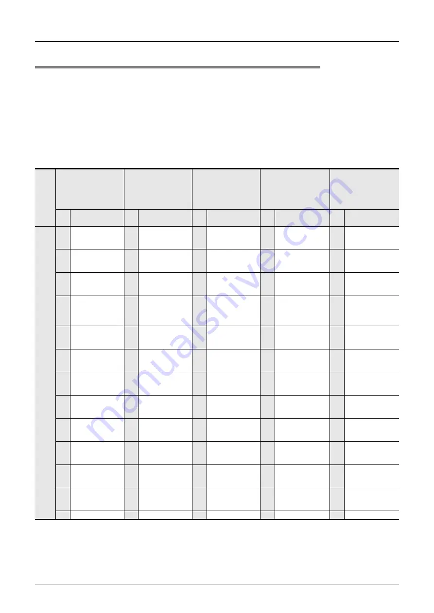
The table below shows the parameters corresponding to each communication port.
- The PU port is common in the V500, F500, A500, and E500 Series.
- In the E500 Series, only the PU port is provided.
- In the V500, F500, and A500 Series, communication parameters for the FR-A5NR computer link are
provided.
- In the S500 Series containing RS-485 communication, the following parameters are applicable.
- In the D700 and E700 Series, communication parameters for the PU port are provided.
- In the E700 Series, communication parameters for the FR-E7TR computer link can be used.
- In the F800, A800, F700, and A700 Series, communication parameters for the built-in RS-485 terminal
are provided.
Funct
ion
FREQROL V500,
F500, A500 and E500
Series (PU port)
FREQROL V500,
F500 and A500
Series (FR-A5NR
computer link)
FREQROL S500
Series (Built-in port
in accordance with
RS-485)
FREQROL D700
and E700 Series
(PU port)
(FR-E7TR computer
link)
FREQROL F800,
A800, F700
and A700 Series
(Built-in RS-485
terminal)
Pr
No.
Name
Pr
No.
Name
Pr
No.
Name
Pr
No.
Name
Pr
No.
Name
Com-
muni-
cation
type
117
Communication
station number
331
Communication
station number
n1
331
Communication
station number
117
PU communication
station number
331
RS-485
communication
station
118
Communication
speed
332
Communication
speed
n2
332
Communication
speed
118
PU communication
speed
332
RS-485
communication
speed
119
Stop bit length/
Data length
333
Stop bit length/
Data length
n3
333
Stop bit length/
Data length
119
PU communication
stop bit length
333
RS-485
communication stop
bit length
120
Parity check
presence/absence
334
Parity check
presence/absence
n4
334
Parity check
presence/absence
120
PU communication
parity check
334
RS-485
communication
parity check
selection
121
Number of
communication
retries
335
Number of
communication
retries
n5
335
Number of times of
communication
retries
121
Number of PU
communication
retries
335
RS-485
communication
number of retries
122
Communication
check time interval
336
Communication
check time interval
n6
336
Communication
check time interval
122
PU communication
check time interval
336
RS-485
communication
check time interval
123 Waiting time setting 337 Waiting time setting n7
337 Waiting time setting 123
PU communication
waiting time setting
337
RS-485
communication
waiting time setting
338
Operation
command right
n8
338
Operation
command right
338
Communication
operation command
source
338
Communication
operation command
source
339
Speed command
write
n9
339
Speed command
right
339
Communication
frequency
command source
339
Communication
speed command
source
340
Link startup mode
selection
n10
340
Link startup mode
selection
340
Communication
startup mode
selection
340
Communication
startup mode
selection
124
CR, LF presence/
absence selection
341
CR, LF presence/
absence selection
n11
341
Absence/presence
of CR and LF
124
PU communication
CR/LF presence/
absence selection
341
RS-485
communication CR/
LF selection
342 E
2
PROM write
selection
n12
342
E
2
PROM write
selection
342
Communication
EEPROM write
selection
342
Communication
EEPROM write
selection
549 Protocol selection
549 Protocol selection
Summary of Contents for FX-485ADP
Page 2: ......
Page 120: ...B 2 FX Series PLC User s Manual Data Communication Edition N N Network ...
Page 188: ...C 2 FX Series PLC User s Manual Data Communication Edition Parallel Link ...
Page 244: ...D 2 FX Series PLC User s Manual Data Communication Edition Computer Link ...
Page 344: ...E 2 FX Series PLC User s Manual Data Communication Edition Inverter Communication ...
Page 700: ...H 2 FX Series PLC User s Manual Data Communication Edition Programming Communication ...
Page 752: ...I 2 FX Series PLC User s Manual Data Communication Edition Remote Maintenance ...
Page 817: ......

