F-46
FX Series PLC User's Manual - Data Communication Edition
Non-Protocol Communication (RS/RS2 Instruction)
6 Creating Programs (RS Instruction)
6.2 How to Use RS Instruction
6.2
How to Use RS Instruction
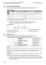
This section explains the function, operation and programming method of RS instruction.
1. Applicable devices
: Applicable only in FX
3G
, FX
3GC
, FX
3U
, FX
3UC
PLCs.
m, n: 0 to 4096 points in FX
2N
, FX
2NC
, FX
3S
, FX
3G
, FX
3GC
, FX
3U
and FX
3UC
PLCs
(However, "m + n" should not be more than 8000 points in FX
2N
and FX
2NC
PLCs.)
0 to 256 points in FX
2
(FX), FX
2C
, FX
0N
, FX
1S
, FX
1N
and FX
1NC
PLCs
2. Program example
6.2.1
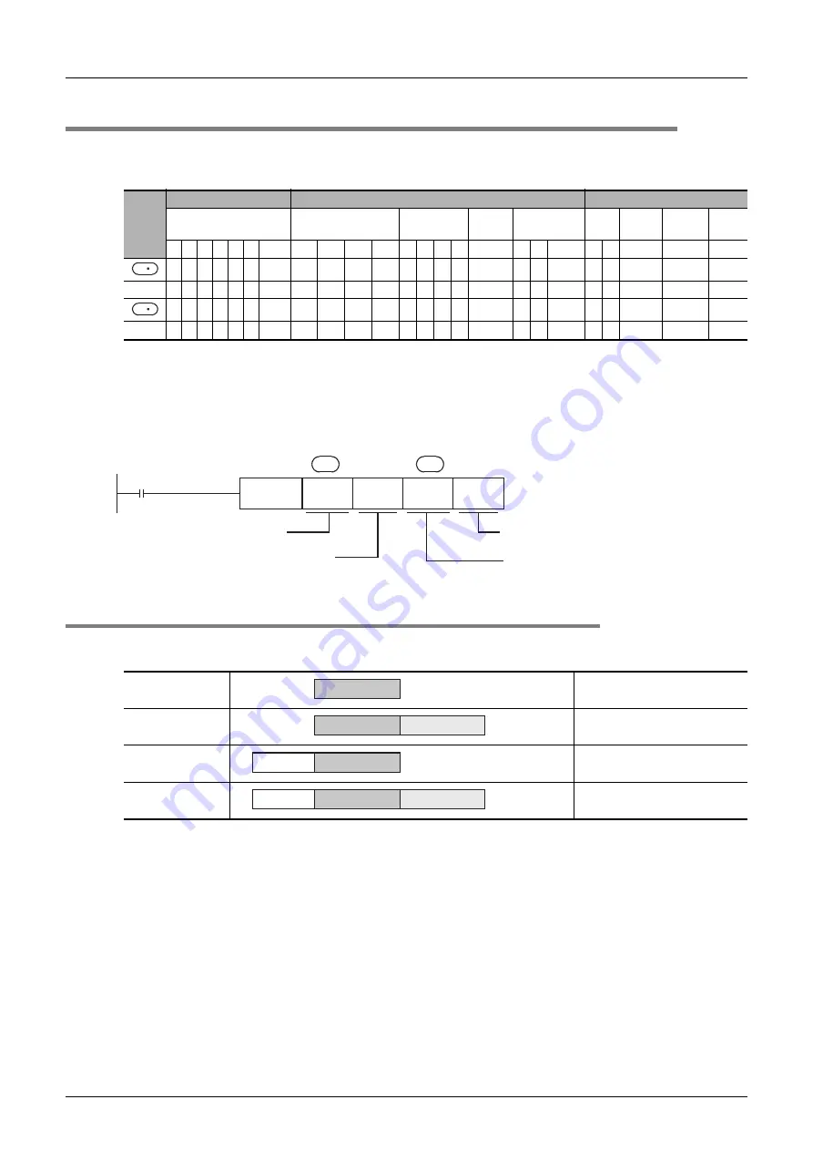
Applicable frames
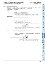
Message frames used in communication can be selected by setting the communication format.
The table below shows the message frames applicable to the RS instruction.
1. Header
When "header provided" is selected in the communication format settings, the lowest-order byte of D8124 is
used.
When data is sent, the lowest-order byte of D8124 is added at the head of the specified send data to be sent.
When data is received, receiving begins when the data on lowest-order byte of D8124 is received.
2. Terminator
When "terminator provided" is selected in the communication format settings, the lowest-order byte of D8125
is used.
When data is sent, the lowest-order byte of D8125 is added at the end of the specified send data.
When data is received, receiving is completed
*1
when the data on lowest-order byte of D8125 is received.
*1.
Receiving is completed also when the amount of received data specified by the RS instruction is
received or when the receiving of data is suspended and the next set of data is not executed within the
timeout time set by D8129.
Oper-
and
Type
Bit Devices
Word Devices
Others
System/User
Digit Specification
System/User
Special
Unit
Index
Con-
stant
Real
Number
Charac-
ter String
Pointer
X Y M T C S D
.b KnX KnY KnM KnS T C D R U
\G
V Z Modify K H
E
"
"
P
m
n
1
Header: Not provided
Terminator: Not provided
2
Header: Not provided
Terminator: Provided
3
Header: Provided
Terminator: Not provided
4
Header: Provided
Terminator: Provided
S
D
M0
FNC 80
RS
D100
D0
D200
D1
S
D
m
n
Head device storing send data
Head device storing receive data
Amount of received data: 0 to 4096 points
(0 to 256 points in FX
2
(FX), FX
2C
, FX
0N
,
FX
1S
, FX
1N
and FX
1NC
PLCs)
Number of send data: 0 to 4096 points
(0 to 256 points in FX
2
(FX), FX
2C
, FX
0N
,
FX
1S
, FX
1N
and FX
1NC
PLCs)
Data
Data
Terminator
Data
Header
Data
Terminator
Header
Summary of Contents for FX-485ADP
Page 2: ......
Page 120: ...B 2 FX Series PLC User s Manual Data Communication Edition N N Network ...
Page 188: ...C 2 FX Series PLC User s Manual Data Communication Edition Parallel Link ...
Page 244: ...D 2 FX Series PLC User s Manual Data Communication Edition Computer Link ...
Page 344: ...E 2 FX Series PLC User s Manual Data Communication Edition Inverter Communication ...
Page 700: ...H 2 FX Series PLC User s Manual Data Communication Edition Programming Communication ...
Page 752: ...I 2 FX Series PLC User s Manual Data Communication Edition Remote Maintenance ...
Page 817: ......

