F-50
FX Series PLC User's Manual - Data Communication Edition
Non-Protocol Communication (RS/RS2 Instruction)
6 Creating Programs (RS Instruction)
6.2 How to Use RS Instruction
6.2.4
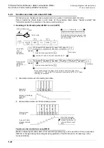
Operation when data is sent
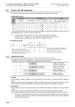
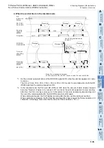
When the sending request flag (M8122) is set to ON while RS instruction is driven, the PLC sends the data
stored in the data registers
to (
+m-1) specified by the RS instruction.
When sending of the data is complete, the sending request flag (M8122) is automatically set to OFF.
1. Time at which sending is started
When RS instruction is executed after the sending request flag (M8122) is set to ON, the PLC starts to send.
When sending begins, the PLC sends the data stored in the data registers specified by the RS instruction in
interrupt processing regardless of the operation cycle.
2. Time at which sending is completed
When all send data is sent, sending is completed.
(If the terminator is set, the terminator is included in the send data.)
3. Cautions on sending
When sending data, observe the following cautions
1) While the sending request flag (M8122) is ON, do not change the amount of send data or contents of
send data.
2) Do not set the sending request flag (M8122) to OFF in a sequence program.
If the send data is changed while the sending request flag (M8122) is ON or if the sending request flag
(M8122) is set to OFF in a sequence program, correct data will not be sent.
6.2.5
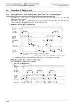
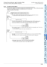
Operation when data is received
When RS instruction is executed, the PLC waits to receive. When the PLC receives data from the connected
equipment and receiving is completed, the receiving complete flag (M8123) is set to ON.
When the PLC receives data, it stores the received data to the data registers
to (
+n-1) specified
by the RS instruction.
While the receiving complete flag (M8123) is ON, the PLC cannot receive new data.
1. Time at which receiving is started
When the PLC receives data while it is waiting to receive, it starts receiving data.
When receiving begins, the PLC stores the received data in interrupt processing regardless of the operation
cycle.
When the header (D8124) is specified in the communication format, however, the PLC starts receiving when
it receives the code set in the header. And the PLC stores the received data except the header.
2. Time at which receiving is completed
Receiving is completed in the following three conditions. When either condition is established, receiving is
completed.
1) When the PLC receives as much data as specified by the RS instruction
2) When "terminator provided" is selected in the communication format, and the PLC receives the code set
in the terminator (D8125)
3) When data receiving is suspended and the PLC does not receive the next set of data within the time set
in the time-out time setting device (D8129)
At this time, the time-out check flag (M8129) turns ON.
(The time-out check flag is not provided in FX
2N
PLC before Ver. 2.00, and FX
2
(FX), FX
2C
, FX
0N
PLCs.)
S
S
D
D
Summary of Contents for FX-485ADP
Page 2: ......
Page 120: ...B 2 FX Series PLC User s Manual Data Communication Edition N N Network ...
Page 188: ...C 2 FX Series PLC User s Manual Data Communication Edition Parallel Link ...
Page 244: ...D 2 FX Series PLC User s Manual Data Communication Edition Computer Link ...
Page 344: ...E 2 FX Series PLC User s Manual Data Communication Edition Inverter Communication ...
Page 700: ...H 2 FX Series PLC User s Manual Data Communication Edition Programming Communication ...
Page 752: ...I 2 FX Series PLC User s Manual Data Communication Edition Remote Maintenance ...
Page 817: ......


