F-71
FX Series PLC User's Manual - Data Communication Edition
Non-Protocol Communication (RS/RS2 Instruction)
8 Creating Programs (RS2 Instruction)
8.2 How to Use RS2 Instruction
A
Comm
on I
te
ms
B
N:
N N
etwo
rk
C
Paral
le
l Li
nk
D
Com
puter Li
nk
E
In
verter
C
omm
uni
cation
F
N
on-Proto
col
C
ommunicati
on
(R
S/RS
2 Instru
ction
)
G
No
n-
Protoc
ol
Co
mmuni
ca
tion
(FX
2N
-2
32IF)
H
Programm
ing
Comm
uni
cation
I
Re
mo
te
Ma
intenance
Apx.A
D
isco
nti
nued
models
8.2.6
Sum check code
The sum check code indicates a two-digit ASCII code converted from the lowest-order byte (8-bit) of the
result (sum) acquired by adding the sum check target data as hexadecimal data.
By setting a parameter, set whether or not the sum check code is added in the message.
• When "sum check provided" is selected, the sum check code is added in the message during sending.
During receiving, the sum check code is compared with the value calculated from the received data to
check the received data.
• When "sum check not provided" is selected, the sum check code is not added, so the received data is not
checked either.
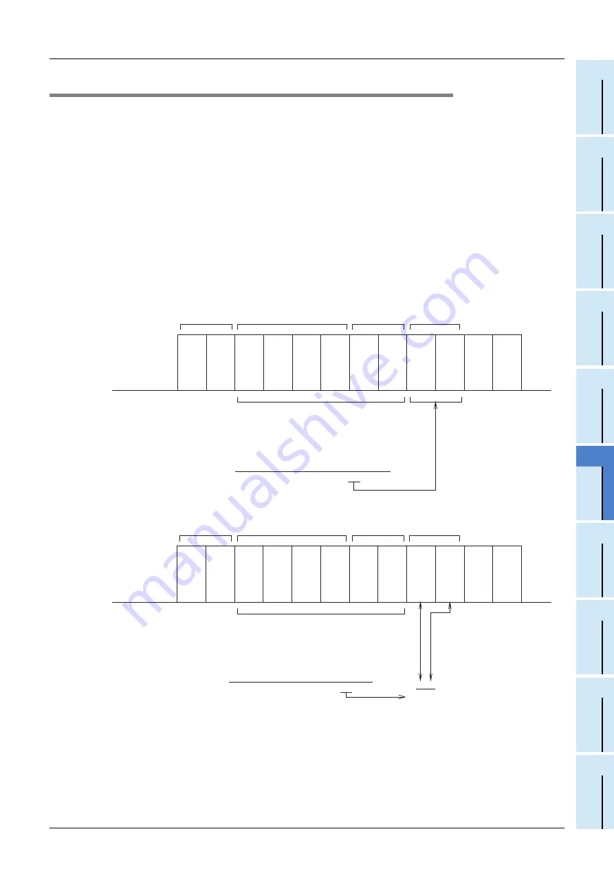
A calculation example of the sum check code is shown below.
Example: When the communication format (parameters) is set as follows
- Control line not provided
- Headers provided [DLE+STX (D8410: 0210H, D8411: 0000H)]
- Terminators provided [DLE+ETX (D8412: 0310H, D8413: 0000H)]
In the case of send data
In the case of receive data
Sum check code target
D100 lowest-order bits
31H
D100 highest-order byte
32H
D101 lowest-order byte
33H
D101 highest-order byte
34H
D8412 lowest-order byte
10H (DLE)
D8412 highest-order byte
03H (ETX)
DDH
Converted into ASCII codes
Send data
The order is
different from
the data area.
D8410
lowest
-order
byte
D8410
highest
-order
byte
D100
lowest
-order
byte
D100
highest
-order
byte
D101
lowest
-order
byte
D101
highest
-order
byte
D8412
lowest
-order
byte
D8412
highest
-order
byte
CR
LF
Sum
highest
-order
byte
Sum
lowest
-order
byte
Header
Data area
Terminator
Sum data
. . . . .
DLE
STX
31H
32H
33H
34H
DLE
ETX
44H
44H
Sum check code target
EDH
Compared
Receive data
4544H
Converted into ASCII codes
The order is
different from
the data area.
D200 lowest-order bits
35H
D200 highest-order byte
36H
D201 lowest-order byte
37H
D201 highest-order byte
38H
D202 lowest-order byte
10H
D202 highest-order byte
03H
DLE
D8410
lowest
-order
byte
STX
D8410
highest
-order
byte
35H
D200
lowest
-order
byte
36H
D200
highest
-order
byte
37H
D201
lowest
-order
byte
38H
D201
highest
-order
byte
DLE
D202
lowest
-order
byte
ETX
D202
highest
-order
byte
CR
LF
45H
highest
-order
byte
44H
lowest
-order
byte
Header
Data area
Terminator
D8414
Sum data
. . . . .
Sum
Sum
D8414
Summary of Contents for FX-485ADP
Page 2: ......
Page 120: ...B 2 FX Series PLC User s Manual Data Communication Edition N N Network ...
Page 188: ...C 2 FX Series PLC User s Manual Data Communication Edition Parallel Link ...
Page 244: ...D 2 FX Series PLC User s Manual Data Communication Edition Computer Link ...
Page 344: ...E 2 FX Series PLC User s Manual Data Communication Edition Inverter Communication ...
Page 700: ...H 2 FX Series PLC User s Manual Data Communication Edition Programming Communication ...
Page 752: ...I 2 FX Series PLC User s Manual Data Communication Edition Remote Maintenance ...
Page 817: ......

