F-75
FX Series PLC User's Manual - Data Communication Edition
Non-Protocol Communication (RS/RS2 Instruction)
8 Creating Programs (RS2 Instruction)
8.4 Important Points in Creating Programs
A
Comm
on I
te
ms
B
N:
N N
etwo
rk
C
Paral
le
l Li
nk
D
Com
puter Li
nk
E
In
verter
C
omm
uni
cation
F
N
on-Proto
col
C
ommunicati
on
(R
S/RS
2 Instru
ction
)
G
No
n-
Protoc
ol
Co
mmuni
ca
tion
(FX
2N
-2
32IF)
H
Programm
ing
Comm
uni
cation
I
Re
mo
te
Ma
intenance
Apx.A
D
isco
nti
nued
models
8.4
Important Points in Creating Programs
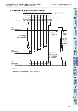
1) The RS2 instruction can be used as many times as necessary in a program, but make sure that only one
RS2 instruction is driven in each communication port at a time.
For multiple RS instructions to be driven, make sure the OFF time is longer than one scan time.
2) Do not use another instruction (such as a RS instruction or IVDR instruction) which uses the same
communication port. If such an instruction is used, communication may not function normally.
3) While a RS2 instruction is being driven, change of D8370, D8400 or D8420 is prohibited.
To change D8370, D8400 or D8420, set the RS2 instruction to OFF, set D8400 or D8420 to "0", and then
set a new value to D8400 or D8420.
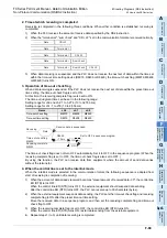
4) In the interlink mode, set the amount of received data "n" to "31" or more.
If it is set to "30" or less, the control line ER (DTR) is set to OFF as soon as the PLC receives data.
5) FX
3S
, FX
3G
, FX
3GC
, FX
3U
and FX
3UC
PLCs execute full-duplex, bidirectional communication. When
using half-duplex, bidirectional communication, pay attention not to turn ON the sending request flag
while receiving.
6) When using the header and terminator, set them before driving the RS2 instruction. Do not change the
setting while the RS2 instruction is being driven.
7) When RS-485 communication is executed in FX
3U
and FX
3UC
PLCs, it may take 300
s until the PLC
starts receiving after it has completed sending.
Assure 300
s or more in counterpart equipment as the period from completion of receiving to start of
sending.
8.5
Communication Error
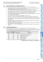
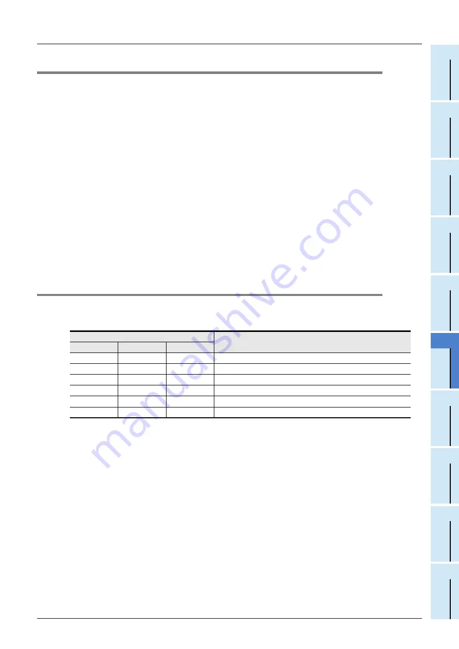
When a communication error occurs, the error flag M8062 turns ON during communication using ch0, the
error flag M8063 turns ON during communication using ch1, or the error flag M8438 turns ON during
communication using ch2. D8063 or D8438 stores the error code respectively.
Confirm the contents in "Chapter 11. Troubleshooting".
Error code
Description
D8062 (ch0)
D8063 (ch1)
D8438 (ch2)
6201
6301
3801
Parity error, overrun error or framing error
6202
6302
3802
Defective communication character
6203
6303
3803
Receive data sum mismatch
6204
6304
3804
Defective data format
6205
6305
3805
Defective command
6206
6306
3806
Monitoring timeout
Summary of Contents for FX-485ADP
Page 2: ......
Page 120: ...B 2 FX Series PLC User s Manual Data Communication Edition N N Network ...
Page 188: ...C 2 FX Series PLC User s Manual Data Communication Edition Parallel Link ...
Page 244: ...D 2 FX Series PLC User s Manual Data Communication Edition Computer Link ...
Page 344: ...E 2 FX Series PLC User s Manual Data Communication Edition Inverter Communication ...
Page 700: ...H 2 FX Series PLC User s Manual Data Communication Edition Programming Communication ...
Page 752: ...I 2 FX Series PLC User s Manual Data Communication Edition Remote Maintenance ...
Page 817: ......

