F-91
FX Series PLC User's Manual - Data Communication Edition
Non-Protocol Communication (RS/RS2 Instruction)
12 Related Data
12.2 Details of related devices (RS instruction)
A
Comm
on I
te
ms
B
N:
N N
etwo
rk
C
Paral
le
l Li
nk
D
Com
puter Li
nk
E
In
verter
C
omm
uni
cation
F
N
on-Proto
col
C
ommunicati
on
(R
S/RS
2 Instru
ction
)
G
No
n-
Protoc
ol
Co
mmuni
ca
tion
(FX
2N
-2
32IF)
H
Programm
ing
Comm
uni
cation
I
Re
mo
te
Ma
intenance
Apx.A
D
isco
nti
nued
models
12.2
Details of related devices (RS instruction)
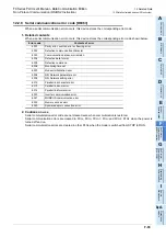
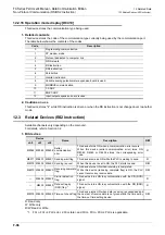
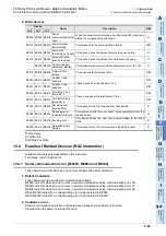
This section explains devices used during non-protocol communication.
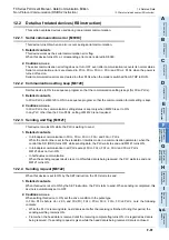
12.2.1 Serial communication error [M8063]
This device turns ON when an error occurs during serial communication.
1. Detailed contents
This device works as the serial communication error flag.
When this device turns ON, a corresponding error code is stored in D8063.
2. Cautions on use
The serial communication error flag does not turn OFF even after communication recovers its normal status.
Serial communication errors are cleared in FX
3S
, FX
3G
, FX
3GC
, FX
3U
and FX
3UC
PLCs when the power is
turned off and on.
Serial communication errors are cleared in other PLCs when the mode is switched from STOP to RUN.
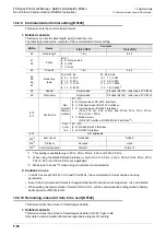
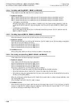
12.2.2 Communication setting keep [M8120]
Set this device to ON in a sequence program so that the communication setting is kept (for FX
0N
PLCs).
1. Detailed contents
In FX
0N
PLCs, set M8120 to ON in a sequence program so that the communication format setting is kept.
2. Cautions on use
In FX
0N
PLCs, the communication setting status is kept only when M8120 is set to ON.
In any PLC other than the FX
0N
PLCs, setting of M8120 is not required.
12.2.3 Sending wait flag [M8121]
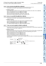
This device remains ON while the PLC is waiting to send.
1. Detailed contents
• In full-duplex communication in FX
3S
, FX
3G
, FX
3GC
, FX
3U
and FX
3UC
PLCs
While the control line is set to the standard or interlink mode in a communication parameter, when the
control line DR (DSR) turns OFF while sending data, the PLC waits to send and M8121 turns ON.
• In full-duplex communication in all PLCs except FX
3S
, FX
3G
, FX
3GC
, FX
3U
and FX
3UC
PLCs
M8121 does not turn ON.
• In half-duplex communication
When the sending request device is set to ON while data is being received, the PLC waits to send and
M8121 turns ON.
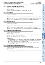
12.2.4 Sending request [M8122]
When this device is set to ON by the SET instruction, the PLC starts to send.
1. Detailed contents
When this device is set to ON by the SET instruction, the PLC starts to send. When sending is completed, this
device is automatically set to OFF.
2. Cautions on use
When setting this device to ON, set the drive condition in the pulse type.
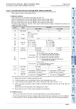
In FX
2N
PLCs before Ver. 2.00, and FX
2
(FX), FX
2C
, FX
0N
, FX
1S
, FX
1N
, FX
1NC
PLCs, note the following
contents:
• While the PLC is receiving data, next data is sent after the receiving is finished. During this period, the
sending wait flag remains ON.
• From when the head data is received until the receiving complete flag turns ON, it is regarded as data is
being received. If a sending request is given while the head data is being received, data is confused.
Summary of Contents for FX-485ADP
Page 2: ......
Page 120: ...B 2 FX Series PLC User s Manual Data Communication Edition N N Network ...
Page 188: ...C 2 FX Series PLC User s Manual Data Communication Edition Parallel Link ...
Page 244: ...D 2 FX Series PLC User s Manual Data Communication Edition Computer Link ...
Page 344: ...E 2 FX Series PLC User s Manual Data Communication Edition Inverter Communication ...
Page 700: ...H 2 FX Series PLC User s Manual Data Communication Edition Programming Communication ...
Page 752: ...I 2 FX Series PLC User s Manual Data Communication Edition Remote Maintenance ...
Page 817: ......

