F-102
FX Series PLC User's Manual - Data Communication Edition
Non-Protocol Communication (RS/RS2 Instruction)
12 Related Data
12.4 Details of Related Devices (RS2 Instruction)
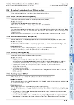
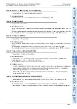
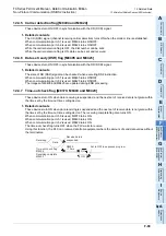
12.4.10 Amount of remaining send data [D8372, D8402 and D8422]
These devices store the amount of remaining send data.
1. Detailed contents
These devices store the amount of remaining send data in 8-bit (1 byte) units.
When communication port ch0 is used, D8372 stores the value.
When communication port ch1 is used, D8402 stores the value.
When communication port ch2 is used, D8422 stores the value.
Only data in communication frames are regarded as the targets of counting.
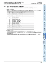
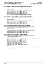
12.4.11 Amount of data already received [D8373, D8403 and D8423]
These devices store the amount of data already received.
1. Detailed contents.
These devices stores the amount of data already received in 8-bit (1 byte) units.
When communication port ch0 is used, D8373 stores the value.
When communication port ch1 is used, D8403 stores the value.
When communication port ch2 is used, D8423 stores the value.
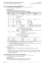
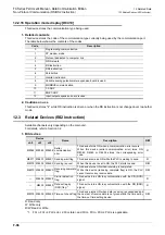
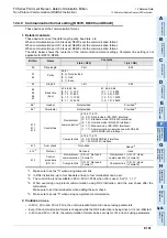
12.4.12 Communication parameter display [D8405 and D8425]
These devices store the communication parameters set in the PLC.
1. Detailed contents
When the PLC power is turned ON, these devices store the contents of the communication parameters.
The setting contents are the same as those of the communication format setting device.
When communication port ch1 is used, D8405 stores the contents.
When communication port ch2 is used, D8425 stores the contents.
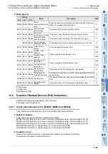
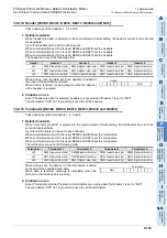
12.4.13 Time-out time setting [D8379, D8409 and D8429]
These devices set the time-out time setting.
1. Detailed contents
These devices set the error evaluation time (in 10 ms units) used when receiving of data is interrupted.
When communication port ch0 is used, D8379 sets the time.
When communication port ch1 is used, D8409 sets the time.
When communication port ch2 is used, D8429 stores the time.
Setting range for ch0 and ch2: 1 to 3,276 (10 to 32,760 ms)
Setting range for ch1: 1 to 255 (10 to 2,550 ms)
When "0" is set in these devices, the time-out time is set to 100 ms.
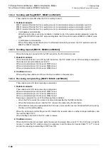
2. Cautions on use
Even if the time-out time setting is changed while the RS2 instruction is being driven, it is not reflected.
After changing the setting, set the RS2 instruction to OFF and ON.
Summary of Contents for FX-485ADP
Page 2: ......
Page 120: ...B 2 FX Series PLC User s Manual Data Communication Edition N N Network ...
Page 188: ...C 2 FX Series PLC User s Manual Data Communication Edition Parallel Link ...
Page 244: ...D 2 FX Series PLC User s Manual Data Communication Edition Computer Link ...
Page 344: ...E 2 FX Series PLC User s Manual Data Communication Edition Inverter Communication ...
Page 700: ...H 2 FX Series PLC User s Manual Data Communication Edition Programming Communication ...
Page 752: ...I 2 FX Series PLC User s Manual Data Communication Edition Remote Maintenance ...
Page 817: ......


