I-23
FX Series PLC User's Manual - Data Communication Edition
Remote Maintenance
4 Wiring
4.1 Wiring Procedure
A
Comm
on I
te
ms
B
N:
N N
etwo
rk
C
Paral
le
l Li
nk
D
Com
puter Li
nk
E
In
verter
C
omm
uni
cation
F
N
on-Proto
col
C
ommunicati
on
(R
S/RS
2 Instru
ction
)
G
No
n-
Protoc
ol
Co
mmuni
ca
tion
(FX
2N
-2
32IF)
H
Programm
ing
Comm
uni
cation
I
Re
mo
te
Ma
intenance
Apx.A
D
isco
nti
nued
models
4. Wiring
This chapter explains the wiring.
4.1
Wiring Procedure
1
Turning OFF the PLC power
Before starting any wiring work, make sure that the PLC power is OFF.
2
Checking the connector shape
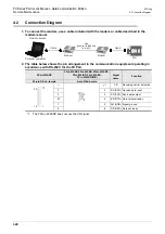
When a cable is included with the modem, check the shape of the RS-232C connector in the
personal computer to be connected, the shape of the connector in the communication equipment
operating in accordance with RS-232C for the PLC, and male or female type.
3
Connecting the RS-232C ports in the modem and the PLC with a cable
Check the shape of the connector (number of pins) in the communication equipment operating in
accordance with RS-232C to be connected to the PLC. Each cable has either connector shape:
- 9-pin D-Sub, female
- 25-pin D-Sub, male
4
Connecting the personal computer and the modem with a cable for remote access
Check the shape of the RS-232C connector (number of pins) on the personal computer for remote access.
Summary of Contents for FX-485ADP
Page 2: ......
Page 120: ...B 2 FX Series PLC User s Manual Data Communication Edition N N Network ...
Page 188: ...C 2 FX Series PLC User s Manual Data Communication Edition Parallel Link ...
Page 244: ...D 2 FX Series PLC User s Manual Data Communication Edition Computer Link ...
Page 344: ...E 2 FX Series PLC User s Manual Data Communication Edition Inverter Communication ...
Page 700: ...H 2 FX Series PLC User s Manual Data Communication Edition Programming Communication ...
Page 752: ...I 2 FX Series PLC User s Manual Data Communication Edition Remote Maintenance ...
Page 817: ......


