


- 7 -
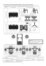
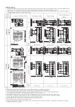
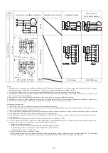
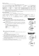
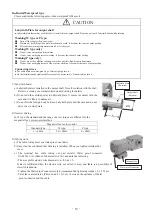
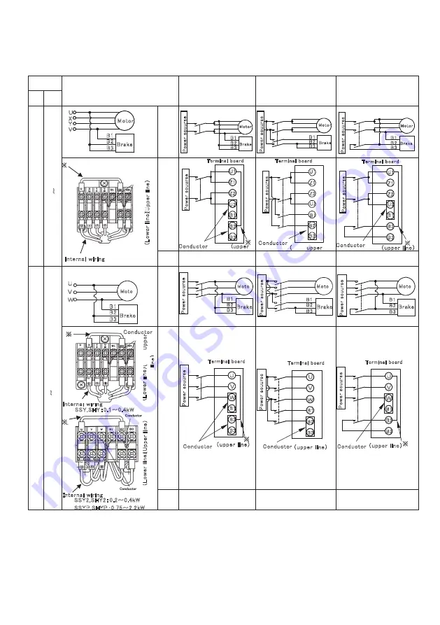
8.Brake Wiring
(1)
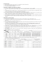
The brake motion delay time (the time before brake start to operate after turning off the power) depends on brake connection method and load
specifications. Select appropriated connection method by considering the functions of machine that attached to motor.
(2)
Braking wires are connected to simultaneous braking method from factory shipment, for the other braking method, please open the terminal box
to change braking connection circuit as shown below.
Motor
Connection condition at delivery
Simultaneous braking
Separate braking
Direct current(immediate
braking)
Input Output
Si
ng
le
p
ha
se
0.1
~
0.
4kW
Ci
rcui
t
Connection
terminals
Inertia
time
0.2
~
0.55 sec.
0.1
~
0.3 sec.
0.01
~
0.03 sec.
Three-ph
ase
0.1
~
2.
2kW
Ci
rcui
t
Connection
terminals
Inertia
time
0.2
~
0.55 sec.
0.1
~
0.3 sec.
0.01
~
0.03 sec.
Notes:
1) Speaking sound, generated from brake lining, is not malfunction and does not affect to performance.
2) For elevator or high accuracy positioning drive, please use direct current (quick) braking method.
3) For simultaneous braking method or direct current (quick) braking method, be sure to connect lead wire (marked with ※)
to the terminals U and B2. And, for separated braking method, be sure to disconnect it.
4) For separated braking method or direct current (quick) braking method, remove one of the connection bar as shown above.
5) For 0.1kW to 2.2kW model, terminal block has 2 lines of terminals (upper and lower line). Be sure to connect power supply
wires to upper line terminals. If connect to the lower line, brake will not be released.
6) Motion delay time may slightly vary from load specification or from brake torque.
7
)
The single phase motor cannot produce the outdoor type.
8) Please select the switch in the brake part by the current of 200V class:DC110V
(
400Vclass
:
DC220V
)
and the DC13(L/R=10ms) class ratings
when you switch off direct current.
B3
B2
B1
※
Terminal board
(
upper
Conductor
(upper
B3
B2
B1
※
B3
B2
B1
B1
B3
B2
Brake
Motor
P
o
w
e
r
s
o
u
u
rs
e
B3
B2
B1
Brake
Motor
B3
B2
B1
Brake
Motor
V
U
X
Y
B3
B2
B1
Brake
Motor
※
Internal wiring
(
L
o
w
e
r
li
n
e
)
(
U
p
p
e
r
li
n
e
)
(upper line)
P
o
w
e
r
s
o
u
u
rs
e
P
o
w
e
r
s
o
u
u
rs
e
P
o
w
e
r
s
o
u
u
rs
e
Conductor
P
o
w
e
r
s
o
u
u
rs
e
P
o
w
e
r
s
o
u
u
rs
e
Conductor
Terminal board
Terminal board
Conductor
R a d Y e l l o w B l a c k W h i t e
B3
B2
B1
Brake
Moto
電
源
B3
B2
B1
Brake
Moto
電
源
B1
B3
B2
Brake
Moto
電
源
W
U
V
B3
B2
B1
Brake
Moto
電
源
B3
B2
B1
W
U
V
電
源
B3
B2
B1
W
U
V
※
電
源
B3
B2
B1
W
U
V
※
(upper line)
※
※
SSY,SHY:0.1~0.4kW
SSY2,SHY2:0.2~0.4kW
SSYP,SHYP:0.75~2.2kW
P
o
w
e
r
s
o
u
u
rs
e
P
o
w
e
r
s
o
u
u
rs
e
P
o
w
e
r
s
o
u
u
rs
e
P
o
w
e
r
s
o
u
u
rs
e
P
o
w
e
r
s
o
u
u
rs
e
P
o
w
e
r
s
o
u
u
rs
e
Terminal board
Terminal board
Terminal board
Conductor
Conductor
Conductor (upper line)
(upper line)
Internal wiring
Internal wiring
(
U
p
p
e
r
li
n
e
)
(
U
p
p
e
r
li
n
e
)
(
L
o
w
e
r
li
n
e
)
(
L
o
w
e
r
li
n
e
)
Conductor
Z2
Z1
U1
U2
Z2
Z1
U1
U2
Z2
Z1
U1
U2
- 7 -
Summary of Contents for GM-SHY
Page 1: ......
Page 2: ......
Page 20: ... 18 ...
Page 21: ... 19 ...
Page 22: ... 20 ...
Page 23: ......
Page 24: ......


