21 - 12
21.3 GOT Side Settings
(3) For GS
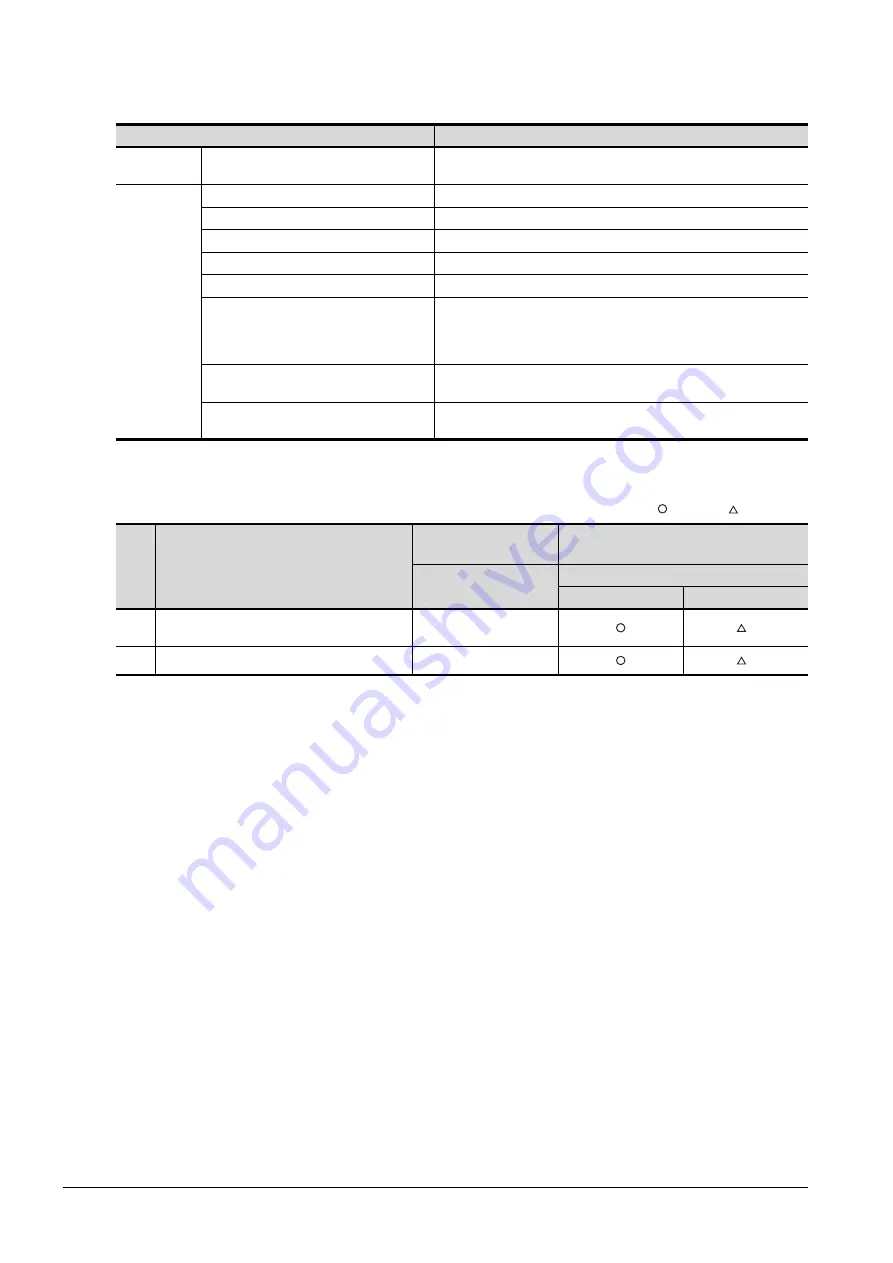
For GS, the combinations of the Ethernet connection and the serial connection are available as shown in the
following table.
The number of channels and the functions that can be used differ depending on the GOT to be used.
The table below shows the allowable combinations of connection types, the number of channels and restricted
functions.
: Allowed : Restricted
*1
When the functions below are used, the connectable number of channels may be restricted depending on the combination of the
functions to be used.
• Barcode function • RFID function
For details, refer to the following.
➠
21.3.4 Determining the GOT side interface (Interface selection)
*2
When a GOT and PLC are connected by Ethernet connection, connecting a GOT and a personal computer by Ethernet is not
allowed.
Connection type
Reference
Ethernet
connection
Ethernet connection
5. Ethernet connection
Serial
connection
Direct CPU connection
6. Direct CPU connection
Computer link connection
7. Computer link connection
CC-Link connection (via G4)
13. CC-Link connection (via G4)
Inverter connection
14. Inverter connection
Servo amplifier connection
15. Servo amplifier connection
Third party PLC connection (Serial connection)
Non-Mitsubishi Electric Products 1
• 4. CONNECTION TO OMRON PLC 4.2 Serial Connection
• 6. CONNECTION TO KEYENCE PLC
• 15. CONNECTION TO PANASONIC INDUSTRIAL DEVICES SUNX PLC
Microcomputer Connection (Serial)
Microcomputers, MODBUS/Fieldbus Products, Peripherals
• 2. MICROCOMPUTER CONNECTION (SERIAL)
MODBUS/RTU connection
Microcomputers, MODBUS/Fieldbus Products, Peripherals
• 5. MODBUS/RTU CONNECTION
Item
Allowable combination of connection types
GOT to be used
Functions that are restricted by the connection
type
*1
GS
FA transparent function
USB
Ethernet
(a)
• Ethernet connection: 1 to 2 channels
• Serial connection: 1 to 2 channels
Max. 2 channels
*2
(b)
• Serial connection: 2 channels
Max. 2 channels
*2
Summary of Contents for GOT2000 Series
Page 2: ......
Page 84: ......
Page 432: ...6 58 6 6 Precautions ...
Page 578: ...9 54 9 6 Precautions ...
Page 726: ...12 84 12 5 Precautions ...
Page 756: ......
Page 822: ...14 66 14 4 Device Range that Can Be Set ...
Page 918: ...15 96 15 7 Precautions ...
Page 930: ...16 12 16 6 Precautions ...
Page 964: ......
Page 1002: ...19 38 19 7 Precautions ...
Page 1022: ...20 20 20 5 Precautions ...
Page 1023: ...MULTI CHANNEL FUNCTION 21 MULTI CHANNEL FUNCTION 21 1 ...
Page 1024: ......
Page 1054: ...21 30 21 5 Multi channel Function Check Sheet ...
Page 1055: ...FA TRANSPARENT FUNCTION 22 FA TRANSPARENT FUNCTION 22 1 ...
Page 1056: ......
Page 1223: ......


