22.7 Personal Computer Side Setting
22 - 79
22
FA TRANSP
ARE
NT FU
NCTION
Step 5.
Network No. and Station No. are not required to be changed (default) because they are not used.
Step 6.
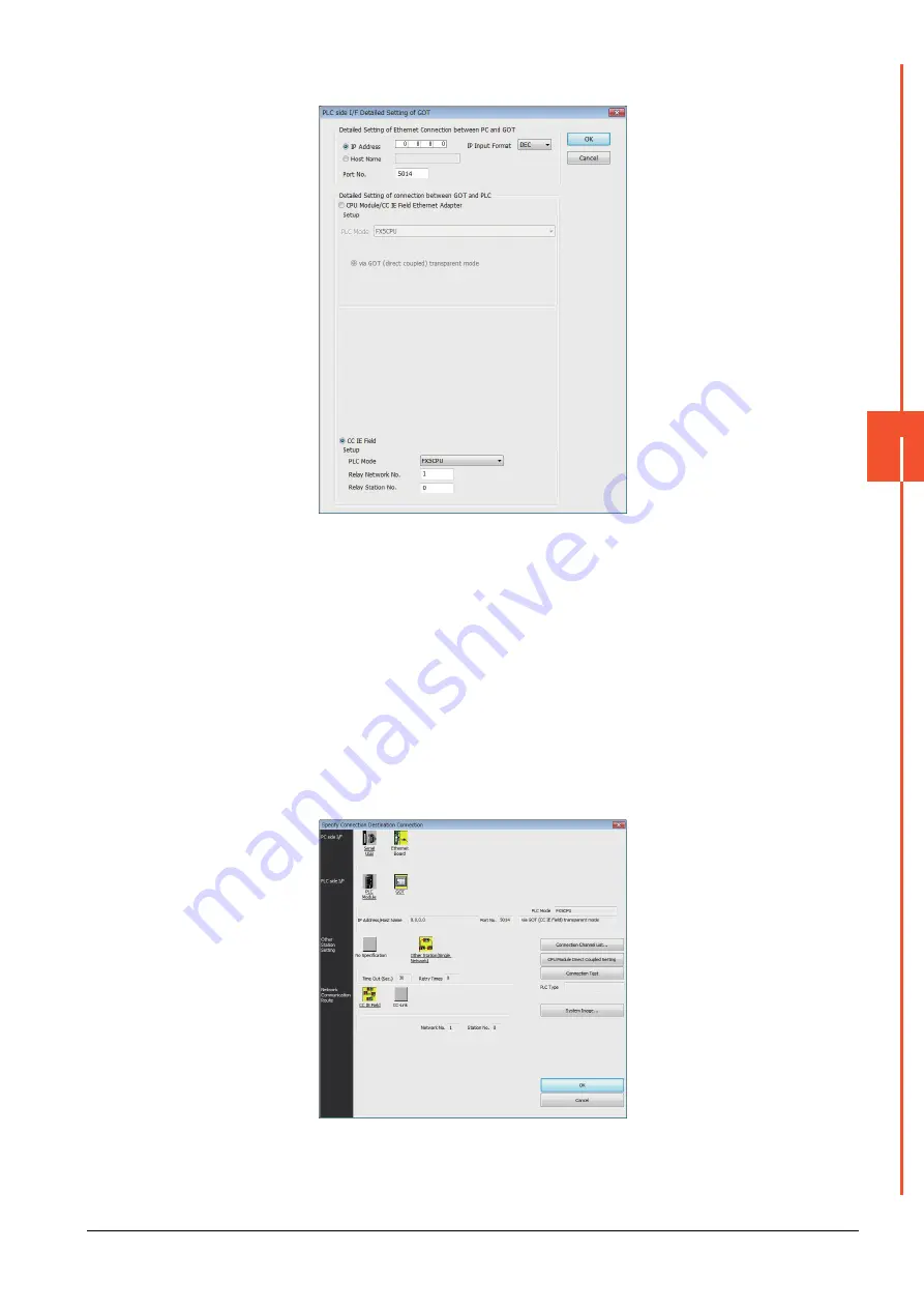
Double-click [GOT] of the PLC side I/F to display [PLC side I/F Detailed Setting of GOT].
Step 7.
Set the IP address and port No. in [Ethernet detail setting for PC and GOT connection].
Set the IP address and port No. to the same as the Ethernet download setting.
➠
2. (2) Ethernet download setting
Step 8.
Check-mark [CC IE Field] in [Detail setting for GOT and PLC connection].
Step 9.
Set the [CPU mode] and [Relay network No.] and [Relay station No.].
• When the target PLC has the same network No. as that of the GOT
Set the number assigned to the PLC that is targeted by using the transparent function and CC-Link
IE field network module.
• When the target PLC has a different network No. from that of the GOT
Set the number assigned the PLC that is used as a relay station and CC-Link IE field network
module.
Summary of Contents for GOT2000 Series
Page 2: ......
Page 84: ......
Page 432: ...6 58 6 6 Precautions ...
Page 578: ...9 54 9 6 Precautions ...
Page 726: ...12 84 12 5 Precautions ...
Page 756: ......
Page 822: ...14 66 14 4 Device Range that Can Be Set ...
Page 918: ...15 96 15 7 Precautions ...
Page 930: ...16 12 16 6 Precautions ...
Page 964: ......
Page 1002: ...19 38 19 7 Precautions ...
Page 1022: ...20 20 20 5 Precautions ...
Page 1023: ...MULTI CHANNEL FUNCTION 21 MULTI CHANNEL FUNCTION 21 1 ...
Page 1024: ......
Page 1054: ...21 30 21 5 Multi channel Function Check Sheet ...
Page 1055: ...FA TRANSPARENT FUNCTION 22 FA TRANSPARENT FUNCTION 22 1 ...
Page 1056: ......
Page 1223: ......


