22.7 Personal Computer Side Setting
22 - 123
22
FA TRANSP
ARE
NT FU
NCTION
Step 6.
Double-click [GOT] of the PLC side I/F to display [PLC side I/F Detailed Setting of GOT].
Step 7.
PLC side I/F Detailed Setting of GOT
Mark the [via GOT(Ethernet) transparent mode] checkbox and click [Set].
Step 8.
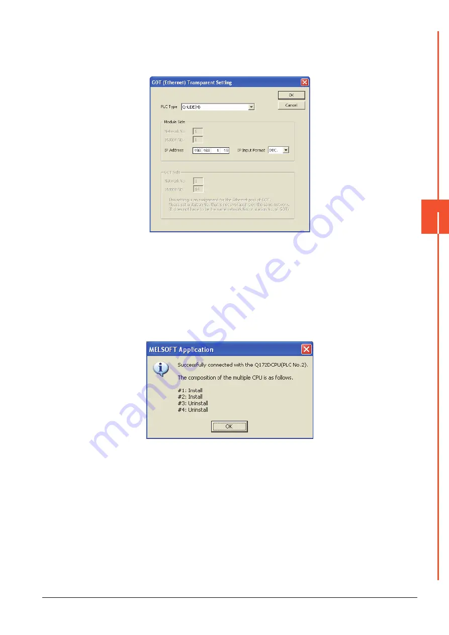
By clicking [Set], the [GOT (Ethernet) Transparent Setting] is displayed.
Here, set the built-in Ethernet port QCPU or Ethernet module, which is firstly connected via a GOT.
Step 9.
Set [QnUDE(H)] or [QJ71E71] for [Type name].
Step 10.
Specify the number for [Network No.] and [Station No.] same as the number assigned to the Ethernet
module.
When [QnUDE(H)] is set for [Type name], the setting is not required.
Step 11.
Specify the IP address for [IP address] same as the IP address assigned to the built-in Ethernet port
QCPU or Ethernet module.
Step 12.
The screen returns to [Transfer setup]. Click [Connection Test] to check if MT Works2 has been
connected to the motion controller (Q mode).
Summary of Contents for GOT2000 Series
Page 2: ......
Page 84: ......
Page 432: ...6 58 6 6 Precautions ...
Page 578: ...9 54 9 6 Precautions ...
Page 726: ...12 84 12 5 Precautions ...
Page 756: ......
Page 822: ...14 66 14 4 Device Range that Can Be Set ...
Page 918: ...15 96 15 7 Precautions ...
Page 930: ...16 12 16 6 Precautions ...
Page 964: ......
Page 1002: ...19 38 19 7 Precautions ...
Page 1022: ...20 20 20 5 Precautions ...
Page 1023: ...MULTI CHANNEL FUNCTION 21 MULTI CHANNEL FUNCTION 21 1 ...
Page 1024: ......
Page 1054: ...21 30 21 5 Multi channel Function Check Sheet ...
Page 1055: ...FA TRANSPARENT FUNCTION 22 FA TRANSPARENT FUNCTION 22 1 ...
Page 1056: ......
Page 1223: ......


