22.7 Personal Computer Side Setting
22 - 125
22
FA TRANSP
ARE
NT FU
NCTION
Step 5.
Set the protocol to TCP. Network No. and Station No. are not required to be changed (default) because
they are not used.
(For bus connection)
Step 6.
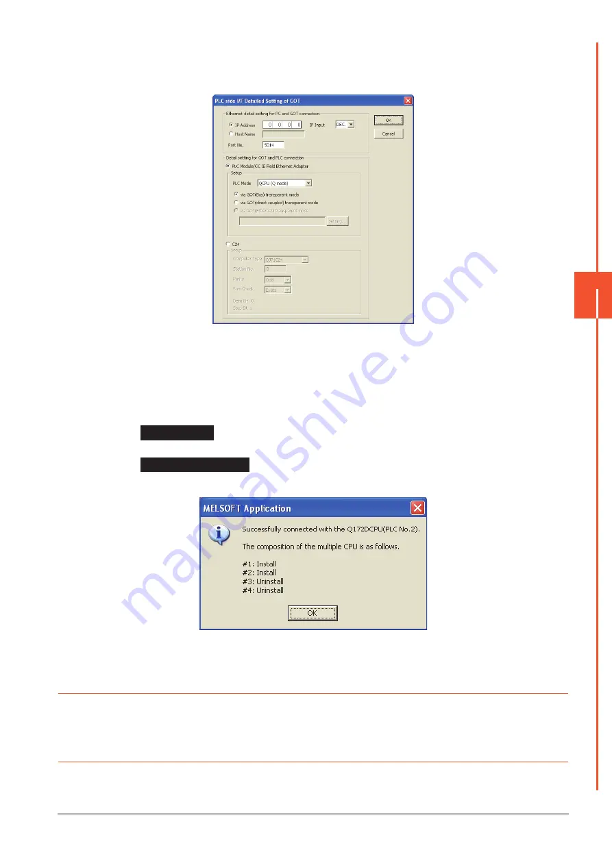
Double-click [GOT] of the PLC side I/F to display [PLC side I/F Detailed Setting of GOT].
Step 7.
Set the IP address and port No. in [Ethernet detail setting for PC and GOT connection].
Set the IP address and port No. to the same as the Ethernet download setting.
➠
22.6.1 (2) Ethernet download setting
Step 8.
Check either of the followings in [Detail setting for GOT and PLC connection].
[via GOT(Bus) transparent mode]
Mark the [via GOT(direct coupled) transparent mode] checkbox.
Step 9.
The screen returns to [Transfer Setup]. Click [Connection Test] to check if MT Works2 has been
connected to the Motion controller (Q mode).
22.7.9
Accessing the servo amplifier by the MR Configurator
Make the FA transparent settings with the of MT Developer.
For details, refer to the following:
➠
22.7.7 Accessing by the MT Developer
22.7.10 Accessing the servo amplifier by the MR Configurator2
Make the FA transparent settings in the MT Works2 communication settings.
For details of MT Works2, refer to the following.
➠
22.7.8 Accessing by the MT Works2
Bus connection
Direct CPU connection
Summary of Contents for GOT2000 Series
Page 2: ......
Page 84: ......
Page 432: ...6 58 6 6 Precautions ...
Page 578: ...9 54 9 6 Precautions ...
Page 726: ...12 84 12 5 Precautions ...
Page 756: ......
Page 822: ...14 66 14 4 Device Range that Can Be Set ...
Page 918: ...15 96 15 7 Precautions ...
Page 930: ...16 12 16 6 Precautions ...
Page 964: ......
Page 1002: ...19 38 19 7 Precautions ...
Page 1022: ...20 20 20 5 Precautions ...
Page 1023: ...MULTI CHANNEL FUNCTION 21 MULTI CHANNEL FUNCTION 21 1 ...
Page 1024: ......
Page 1054: ...21 30 21 5 Multi channel Function Check Sheet ...
Page 1055: ...FA TRANSPARENT FUNCTION 22 FA TRANSPARENT FUNCTION 22 1 ...
Page 1056: ......
Page 1223: ......


