4.1 MELSEC iQ-R Series
4 - 43
4
HOW T
O
MONIT
O
R REDUNT
ANT SYSTEM
■6.
Serial communication module (mounted on remote I/O station) connection (Double-line
configuration)
(1) System configuration example
The following connection example for connecting to the redundant CPU via the remote I/O station connected by
Serial communication module is explained in this section.
(2) Connection method
Connect the serial communication module (mounted on remote I/O station) to the GOT.
➠
7. SERIAL COMMUNICATION CONNECTION
(3) PLC Side Setting (GX Works3)
(a)
Redundant CPU (Master station)
➠
3. Ethernet module (mounted on remote I/O station) connection (Double-line configuration)
(b)
CC-Link IE Field Network Remote Head Module (1st)
➠
3. Ethernet module (mounted on remote I/O station) connection (Double-line configuration)
At [I/O Assignment], replace the Ethernet module with the serial communication module and assign the module.
(c)
CC-Link IE Field Network Remote Head Module (2nd)
➠
3. Ethernet module (mounted on remote I/O station) connection (Double-line configuration)
(4) GOT Side Settings
➠
4. Serial communication module (mounted on remote I/O station) connection (Single
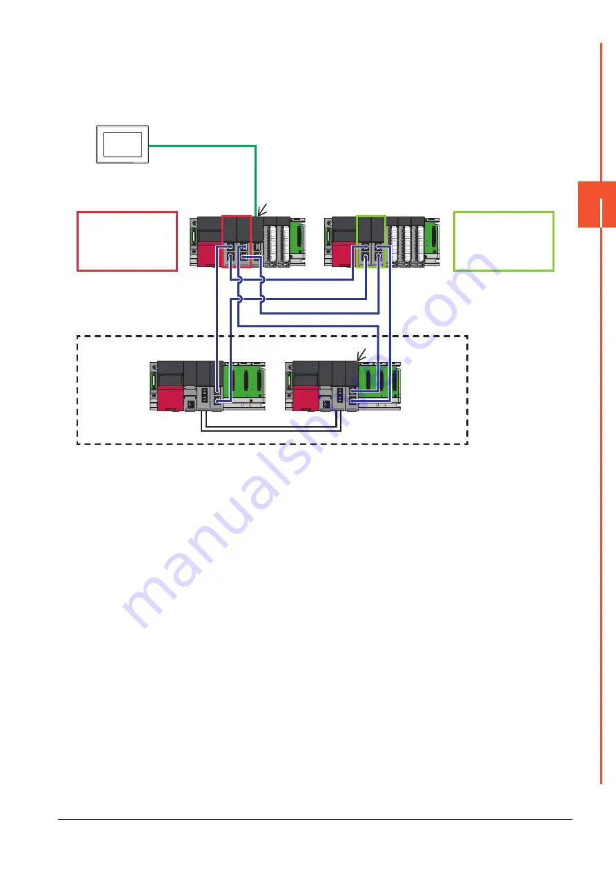
(5) Monitoring target change when system switching occurs in a redundant system
When the system switching occurs, CPU (Network No.: 1, PLC station No.: 1) takes over the control of the Ethernet
network system as the control system.
The GOT automatically starts monitoring accroding to the specified system.
GOT
RS232
Remote I/O station 2nd
[CC-Link IE Field
Network]
N/W No. :1
PC No. :3
7)
4)
4)
Remote I/O station 1st
[CC-Link IE Field
Network]
N/W No. :1
PC No. :2
Control system
(system A)
N/W No. :1
PC No. :0
Control system
(system B)
N/W No. :1
PC No. :1
1) Process CPU
2) Redundant function module
3) Tracking cable
4) CC-Link IE Filed Network remote head module(RJ72GF15-T2(LR))
5) Serial communication module
6) CC-Link IE Filed Network Master/Local module (RJ71GF11-T2(LR))
7) I/O module
CC-Link IE Field Network
(N/W No. :1)
(Redundant system: Pair No.1)
5)
7)
4)
4)
1) 2)
1) 2)
6)
3)
6)
Summary of Contents for GOT2000 Series
Page 2: ......
Page 84: ......
Page 432: ...6 58 6 6 Precautions ...
Page 578: ...9 54 9 6 Precautions ...
Page 726: ...12 84 12 5 Precautions ...
Page 756: ......
Page 822: ...14 66 14 4 Device Range that Can Be Set ...
Page 918: ...15 96 15 7 Precautions ...
Page 930: ...16 12 16 6 Precautions ...
Page 964: ......
Page 1002: ...19 38 19 7 Precautions ...
Page 1022: ...20 20 20 5 Precautions ...
Page 1023: ...MULTI CHANNEL FUNCTION 21 MULTI CHANNEL FUNCTION 21 1 ...
Page 1024: ......
Page 1054: ...21 30 21 5 Multi channel Function Check Sheet ...
Page 1055: ...FA TRANSPARENT FUNCTION 22 FA TRANSPARENT FUNCTION 22 1 ...
Page 1056: ......
Page 1223: ......