4 - 52
4.2 MELSEC Q Series
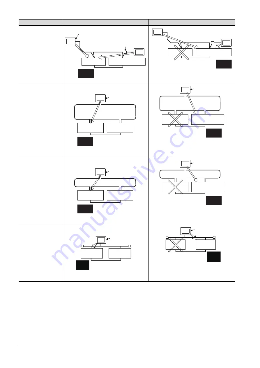
Connection type
Before system switching
After system switching
• CC-Link connection
(intelligent device
station)
• CC-Link connection
(Via G4)
The monitoring target is automatically changed to the control
system PLC CPU.
• MELSECNET/H
connection,
MELSECNET/ 10
connection
(Network system)
By the MELSEC redundant setting, the GOT automatically
changes the monitoring target to the PLC CPU in the control
system.
*2
• CC-Link IE Controller
Network connection
(Network system)
By the MELSEC redundant setting, the GOT automatically
changes the monitoring target to the PLC CPU in the control
system.
*2
• Ethernet connection
By the MELSEC redundant setting, the GOT automatically
changes the monitoring target to the PLC CPU in the control
system.
*2
Intelligent device station
Master station
GOT1
Standby master station
AJ65BT-G4-S3
CC-Link
GOT2
Control
system
Standby
system
Master station
Standby master station
Control
system
Standby
system
GOT1
CC-Link
GOT2
GOT
Station No.3
(normal station)
MELSECNET/H PLC to PLC network
(MELSECNET/H mode or
MELSECNET/10 mode)
Station No.1
(control station)
Station No.2
(normal station)
Control
system
Standby
system
GOT
Station No.3
(normal station)
MELSECNET/H PLC to PLC network
(MELSECNET/H mode or
MELSECNET/10 mode)
Station No.1
(normal station)
Station No.2
(sub control station)
Control
system
Standby
system
GOT
Station No.3
(normal station)
Station No.1
(control station)
Station No.2
(normal station)
Control
system
Standby
system
CC-Link IE Controller Network
GOT
Station No.3
(normal station)
Station No.1
(normal station)
Station No.2
(sub control station)
Control
system
Standby
system
CC-Link IE Controller Network
GOT
Control
system
Standby
system
Station No. 3
Station No. 1
Station No. 2
Ethernet
GOT
Standby
system
Control
system
Station No. 3
Station
No. 1
Station
No. 2
Ethernet
Summary of Contents for GOT2000 Series
Page 2: ......
Page 84: ......
Page 432: ...6 58 6 6 Precautions ...
Page 578: ...9 54 9 6 Precautions ...
Page 726: ...12 84 12 5 Precautions ...
Page 756: ......
Page 822: ...14 66 14 4 Device Range that Can Be Set ...
Page 918: ...15 96 15 7 Precautions ...
Page 930: ...16 12 16 6 Precautions ...
Page 964: ......
Page 1002: ...19 38 19 7 Precautions ...
Page 1022: ...20 20 20 5 Precautions ...
Page 1023: ...MULTI CHANNEL FUNCTION 21 MULTI CHANNEL FUNCTION 21 1 ...
Page 1024: ......
Page 1054: ...21 30 21 5 Multi channel Function Check Sheet ...
Page 1055: ...FA TRANSPARENT FUNCTION 22 FA TRANSPARENT FUNCTION 22 1 ...
Page 1056: ......
Page 1223: ......