4.2 MELSEC Q Series
4 - 61
4
HOW T
O
MONIT
O
R REDUNT
ANT SYSTEM
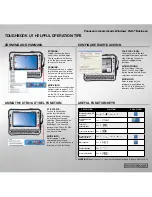
Step 1.
Set the screen switching device of the base screen.
Choose [Common]
[GOT Environmental Setting]
[Screen Switching/Window], and set the internal
device GD100 as the base screen switching device.
(Do not use PLC CPU devices for the screen switching device. If used, the Trigger Action operation of the
GOT may be disabled since the device data of the PLC CPU is overwritten by the device value transferred
with the redundant system tracking function)
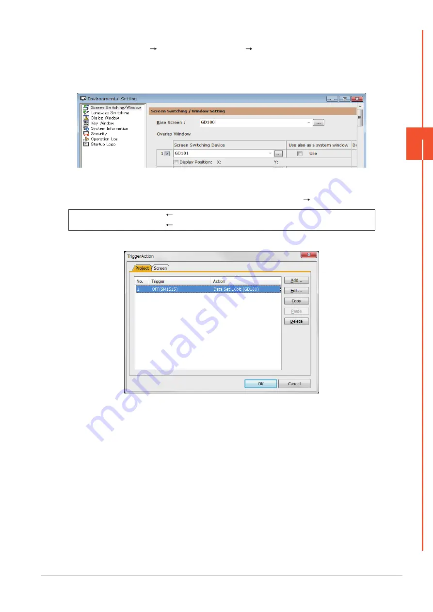
Step 2.
Set the trigger action.
Make the setting so that the base screen 1 is displayed when the connected PLC CPU is the standby
system (SM1515 is OFF) in the project specified by selecting [Common]
[Trigger Action].
Create the trigger action in the project on the Project tab.
Condition 1 : SM1515 (while OFF)
When the SM1515 is OFF, the connected PLC CPU is the standby system.
Operation : GD100=1
The screen switches to the base screen 1.
Summary of Contents for GOT2000 Series
Page 2: ......
Page 84: ......
Page 432: ...6 58 6 6 Precautions ...
Page 578: ...9 54 9 6 Precautions ...
Page 726: ...12 84 12 5 Precautions ...
Page 756: ......
Page 822: ...14 66 14 4 Device Range that Can Be Set ...
Page 918: ...15 96 15 7 Precautions ...
Page 930: ...16 12 16 6 Precautions ...
Page 964: ......
Page 1002: ...19 38 19 7 Precautions ...
Page 1022: ...20 20 20 5 Precautions ...
Page 1023: ...MULTI CHANNEL FUNCTION 21 MULTI CHANNEL FUNCTION 21 1 ...
Page 1024: ......
Page 1054: ...21 30 21 5 Multi channel Function Check Sheet ...
Page 1055: ...FA TRANSPARENT FUNCTION 22 FA TRANSPARENT FUNCTION 22 1 ...
Page 1056: ......
Page 1223: ......