


4.2 MELSEC Q Series
4 - 63
4
HOW T
O
MONIT
O
R REDUNT
ANT SYSTEM
Step 4.
Set the touch switches on the base screen 1.
By using the go to screen switch function, set a touch switch for shifting the screen to the next screen with a
screen touch, when the connected PLC CPU is the control system (SM1515 is ON).
Select [Object]
[Switch]
[Go To Screen Switch] and set the screen switching function.
Set the same size for the touch switch as the base screen size so that touching any place of the screen
enables the switch operation.
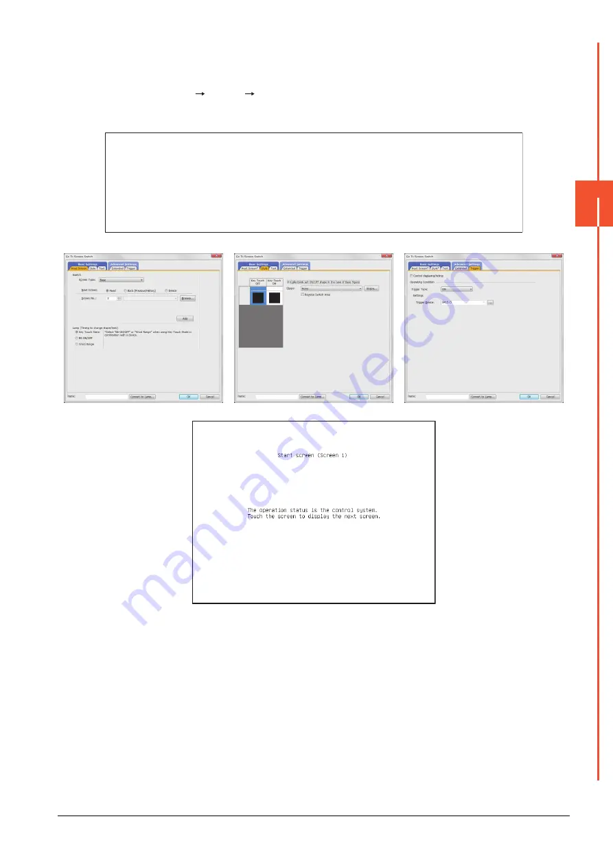
1) Next Screen tab
2) Style tab screen
3) Trigger tab screen
The following shows the created base screen 1.
Next Screen tab
Screen Type
: Base
Go To Screen
: Fixed 2
Style tab
Display Style
: None (Shape)
Trigger tab
Trigger Type
: ON
Trigger Device
: SM1515
Summary of Contents for GOT2000 Series
Page 2: ......
Page 84: ......
Page 432: ...6 58 6 6 Precautions ...
Page 578: ...9 54 9 6 Precautions ...
Page 726: ...12 84 12 5 Precautions ...
Page 756: ......
Page 822: ...14 66 14 4 Device Range that Can Be Set ...
Page 918: ...15 96 15 7 Precautions ...
Page 930: ...16 12 16 6 Precautions ...
Page 964: ......
Page 1002: ...19 38 19 7 Precautions ...
Page 1022: ...20 20 20 5 Precautions ...
Page 1023: ...MULTI CHANNEL FUNCTION 21 MULTI CHANNEL FUNCTION 21 1 ...
Page 1024: ......
Page 1054: ...21 30 21 5 Multi channel Function Check Sheet ...
Page 1055: ...FA TRANSPARENT FUNCTION 22 FA TRANSPARENT FUNCTION 22 1 ...
Page 1056: ......
Page 1223: ......


