1.1 Setting the Communication Interface
1 - 3
1
PREP
ARA
T
O
R
Y PROC
EDURE
S FOR MONIT
O
RING
1.1
Setting the Communication Interface
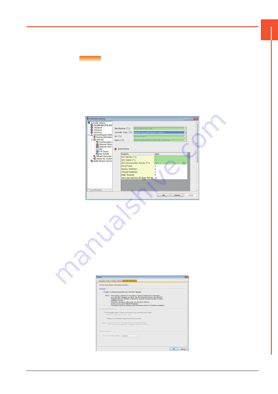
Set the communication interface of GOT and the connected equipment.
When using the GOT at the first time, make sure to set the channel of communication interface and the communication
driver before writing to GOT.
Set the communication interface of the GOT at [Controller Setting] and [I/F Communication Setting] in GT Designer3.
POINT
POINT
POINT
When using the parameter reflection function of MELSOFT Navigator
The system configuration of MELSOFT Navigator can be reflected to the project of GT Designer3
using the parameter function of MELSOFT Navigator.
For details of the parameter functions of MELSOFT Navigator, refer to the following.
➠
Help of MELSOFT Navigator
(1) The color of the cells for the items which are reflected to GT Designer3 from MELSOFT
Navigator changes to green. Set items, which are displayed in green cells, from the
MELSOFT Navigator. When changing in GT Designer3, refer to the following (3).
(2) When setting the communication interface for the connection with the iQ Works untargeted
equipment, set [Set by GT Designer3] to the channel connected at [Configuration detailed
information input] in MELSOFT Navigator and make the settings at [Controller Setting] in GT
Designer3.
(3) To make the items reflected from MELSOFT Navigator editable on GT Designer3, select the
[Option] menu and put a check mark at [Enable an editing of parameters set in MELSOFT
Navigator] in the [iQ Works Interaction] tab.
However, when the items set in MELSOFT Navigator are edited in GT Designer3, the
interaction function with MELSOFT Navigator is unavailable due to a mismatch with the
system configuration of MELSOFT Navigator.
Eliminate mismatches using the parameter verification function etc. before using the
interaction function of MELSOFT Navigator.
Summary of Contents for GOT2000 Series
Page 2: ......
Page 84: ......
Page 432: ...6 58 6 6 Precautions ...
Page 578: ...9 54 9 6 Precautions ...
Page 726: ...12 84 12 5 Precautions ...
Page 756: ......
Page 822: ...14 66 14 4 Device Range that Can Be Set ...
Page 918: ...15 96 15 7 Precautions ...
Page 930: ...16 12 16 6 Precautions ...
Page 964: ......
Page 1002: ...19 38 19 7 Precautions ...
Page 1022: ...20 20 20 5 Precautions ...
Page 1023: ...MULTI CHANNEL FUNCTION 21 MULTI CHANNEL FUNCTION 21 1 ...
Page 1024: ......
Page 1054: ...21 30 21 5 Multi channel Function Check Sheet ...
Page 1055: ...FA TRANSPARENT FUNCTION 22 FA TRANSPARENT FUNCTION 22 1 ...
Page 1056: ......
Page 1223: ......


