6 - 54
6.5 PLC Side Setting
6.5
PLC Side Setting
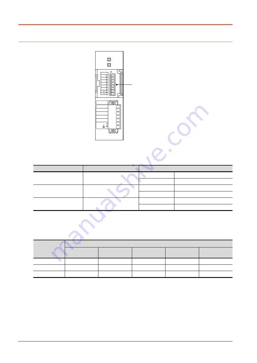
When a GOT and an LCPU are connected via an L6ADP-R4 adapter, set the following communication setting.
6.5.1
L6ADP-R4 adapter settings
Set the communication settings by the DIP switches of the L6ADP-R4 adapter.
*1
SW7 and SW8 are not used.
■1.
DIP switches (SW1 to SW3)
Set the data length, parity bit, and stop bit.
*1
Adjust the settings with GOT settings.
➠
6.4.2 Communication detail settings
■2.
DIP switches (SW4 to SW6)
Set the transmission speed.
*1
Adjust the settings with GOT settings.
➠
6.4.2 Communication detail settings
Setting switch
Description
Setting range
SW1
Data length
*1
OFF
7bit
ON
8bit
SW2
Parity
*1
OFF
Disable
ON
Enable
SW3
Stop bit
*1
OFF
1bit
ON
2bit
Setting switch
Transmission speed
*1
9600
bps
19200
bps
38400
bps
57600
bps
115200
bps
SW4
ON
OFF
ON
OFF
ON
SW5
ON
OFF
OFF
ON
ON
SW6
OFF
ON
ON
ON
ON
DIP SWITCH
*1
SW1 to 8
L6ADP-R4
SD
RD
SW
SDA
SDB
RDA
RDB
SG
(FG)
RS-422/485
ON
DATA 1
2
3
4
5
6
7
8
PARITY
STOP
BAUD0
BAUD1
BAUD2
Summary of Contents for GOT2000 Series
Page 2: ......
Page 84: ......
Page 432: ...6 58 6 6 Precautions ...
Page 578: ...9 54 9 6 Precautions ...
Page 726: ...12 84 12 5 Precautions ...
Page 756: ......
Page 822: ...14 66 14 4 Device Range that Can Be Set ...
Page 918: ...15 96 15 7 Precautions ...
Page 930: ...16 12 16 6 Precautions ...
Page 964: ......
Page 1002: ...19 38 19 7 Precautions ...
Page 1022: ...20 20 20 5 Precautions ...
Page 1023: ...MULTI CHANNEL FUNCTION 21 MULTI CHANNEL FUNCTION 21 1 ...
Page 1024: ......
Page 1054: ...21 30 21 5 Multi channel Function Check Sheet ...
Page 1055: ...FA TRANSPARENT FUNCTION 22 FA TRANSPARENT FUNCTION 22 1 ...
Page 1056: ......
Page 1223: ......


