7.5 PLC Side Setting
7 - 39
7
S
E
RIAL COMMUNICA
TION CONNEC
T
ION
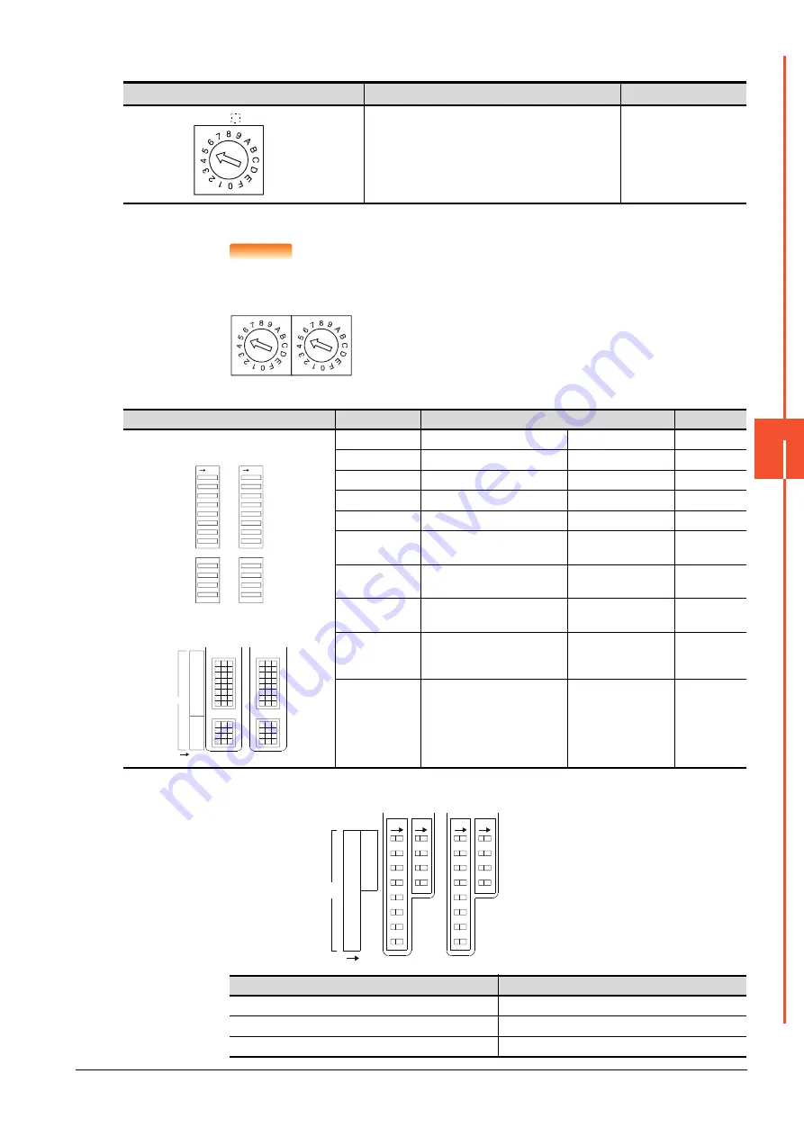
(1) Mode setting switch
*1
The mode switch in the figure is for the AJ71QC24 (N) (-R2/R4).
POINT
POINT
POINT
When connecting a GOT to CH2
Set the CH1 side mode switch to any other than "0" (interlocked operation).
(2) Transmission specifications setting switch
*1
The following shows the layout of switches in the case of the following hardware versions for the module.
Switch settings and switch ON/OFF directions are the same.
Mode setting switch
*1
Description
Set value
Dedicated protocol (Format 5)
(Binary mode)
5
Transmission specifications setting switch
Setting switch
Description
Set value
AJ71QC24(N)
(-R2/R4)
A1SJ71QC24(N)
(N1)(-R2)
*1
SW01
Operation setting
Independent operation
OFF
SW02
Data bit setting
8bits
ON
SW03
Parity bit enable/disable setting
Enable
ON
SW04
Even/odd parity setting
Odd
OFF
SW05
Stop bit setting
1bit
OFF
SW06
Sum check enable/disable
setting
Enable
ON
SW07
Write during RUN enable/disable
setting
Enable
ON
SW08
Setting change enable/disable
Disable
(prohibit)
OFF
SW09
to
SW12
Transmission speed setting
(Consistent with the
GOT side
specifications)
See (a)
SW13
to
SW15
―
The switch is located
on the left side of the
module.
(only on AJ71QC24 (-
R2/R4))
All OFF
Target unit
Hardware version
A1SJ71QC24
Version E hardware or earlier
A1SJ71QC24-R2
Version D hardware or earlier
A1SJ71QC24N, A1SJ71QC24N-R2
Version A hardware
MODE
CH
MODE
CH2
CH1
SW
01
02
03
04
05
06
07
08
09
10
11
12
ON
ON
ON
2
1
4
3
6
5
8
7
10
9
12
11
SW
1
8
2
3
4
5
6
7
9
10
11
12
SW
CH1/2
ON
Summary of Contents for GOT2000 Series
Page 2: ......
Page 84: ......
Page 432: ...6 58 6 6 Precautions ...
Page 578: ...9 54 9 6 Precautions ...
Page 726: ...12 84 12 5 Precautions ...
Page 756: ......
Page 822: ...14 66 14 4 Device Range that Can Be Set ...
Page 918: ...15 96 15 7 Precautions ...
Page 930: ...16 12 16 6 Precautions ...
Page 964: ......
Page 1002: ...19 38 19 7 Precautions ...
Page 1022: ...20 20 20 5 Precautions ...
Page 1023: ...MULTI CHANNEL FUNCTION 21 MULTI CHANNEL FUNCTION 21 1 ...
Page 1024: ......
Page 1054: ...21 30 21 5 Multi channel Function Check Sheet ...
Page 1055: ...FA TRANSPARENT FUNCTION 22 FA TRANSPARENT FUNCTION 22 1 ...
Page 1056: ......
Page 1223: ......


