8 - 22
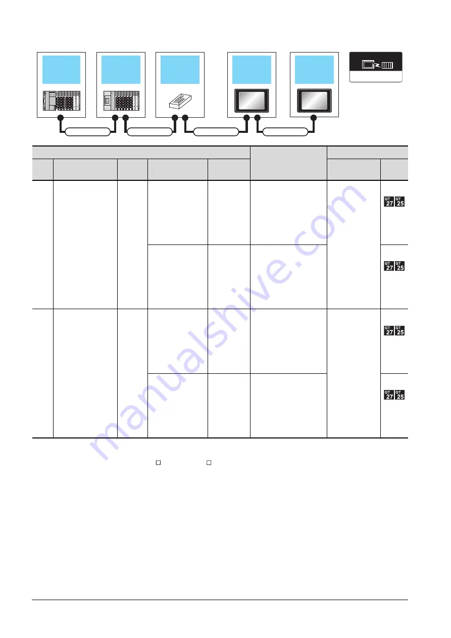
8.2 System Configuration
■2.
When two GOTs are connected
*1
When installing the 1st GOT 30m or more away from the main base unit, the bus connector conversion box is required.
*2
GT 2705-V can be available for terminal.
*3
When using GT15-C EXSS-1 or GT15-C BS, connect as following precautions.
➠
8.4.1 GT15-C [ ] EXSS-1, GT15-C [ ] BS
*4
The number of connectable GOTs is restricted according to the CPU type and the number of intelligent function modules.
➠
8.4.12 When connecting multiple GOTs
PLC
*4
Connection cable 2)
GOT (1st)
*2
Main
base
Extension cable
Extension
base
Connection cable 1)
Bus connector
conversion box
Option device
*5*6*7
Model
Main
base
-
-
-
-
GT15-A370C12B-S1(1.2m)
GT15-A370C25B-S1(2.5m)
GT15-75ABUS2L
GT15-ABUS2
GT15-
A370C12B(1.2m)
GT15-
A370C25B(2.5m)
A7GT-CNB
*1
GT15-C100EXSS-1(10m)
GT15-C200EXSS-1(20m)
*3
Main
base
GT15-A370C12B(1.2m)
GT15-A370C25B(2.5m)
Extension
base
-
-
GT15-C12NB(1.2m)
GT15-C30NB(3m)
GT15-C50NB(5m)
GT15-75ABUS2L
GT15-ABUS2
GT15-AC06B(0.6m)
GT15-AC12B(1.2m)
GT15-AC30B(3m)
GT15-AC50B(5m)
A7GT-CNB
*1
GT15-C100EXSS-1(10m)
GT15-C200EXSS-1(20m)
*3
Extension base
unit
Bus extension
connector box
1st GOT
Main base unit
Connection cable 1)
Connection cable 2)
Extension cable
2nd GOT
Connection cable 3)
Communication driver
Bus(A/QnA)
Summary of Contents for GOT2000 Series
Page 2: ......
Page 84: ......
Page 432: ...6 58 6 6 Precautions ...
Page 578: ...9 54 9 6 Precautions ...
Page 726: ...12 84 12 5 Precautions ...
Page 756: ......
Page 822: ...14 66 14 4 Device Range that Can Be Set ...
Page 918: ...15 96 15 7 Precautions ...
Page 930: ...16 12 16 6 Precautions ...
Page 964: ......
Page 1002: ...19 38 19 7 Precautions ...
Page 1022: ...20 20 20 5 Precautions ...
Page 1023: ...MULTI CHANNEL FUNCTION 21 MULTI CHANNEL FUNCTION 21 1 ...
Page 1024: ......
Page 1054: ...21 30 21 5 Multi channel Function Check Sheet ...
Page 1055: ...FA TRANSPARENT FUNCTION 22 FA TRANSPARENT FUNCTION 22 1 ...
Page 1056: ......
Page 1223: ......


