8 - 30
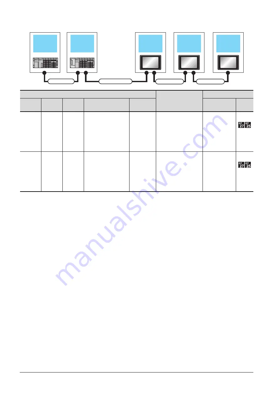
8.2 System Configuration
■3.
When 2 to 3 GOTs are connected
*4
*1
For the extension cables, refer to MELSEC-A/QnA catalog (L(NA)08024).
*2
Use the A168B for the extension base unit.
*3
GT 2705-V can be available for terminal.
*4
The number of connectable GOTs is restricted according to the CPU type and the number of intelligent function modules.
➠
8.4.12 When connecting multiple GOTs
PLC
*3
Connection cable 2)
GOT (1st)
*3
Main base
Extension
cable
*1
Extension
base
*2
Connection cable 1)
Bus connector
conversion box
Option device
*6*7*8
Model
Main base
-
-
-
-
GT15-A1SC07B(0.7m)
GT15-A1SC12B(1.2m)
GT15-A1SC30B(3m)
GT15-75ABUS2L
GT15-ABUS2
Main base
Extension
cable
Extension
base
-
-
GT15-A1SC07B(0.7m)
GT15-A1SC12B(1.2m)
GT15-A1SC30B(3m)
GT15-75ABUS2L
GT15-ABUS2
Main base unit
Extension base
unit
Connection cable 2)
Connection cable 3)
Extension cable
1st GOT
2nd GOT
Connection cable 4)
3rd GOT
Summary of Contents for GOT2000 Series
Page 2: ......
Page 84: ......
Page 432: ...6 58 6 6 Precautions ...
Page 578: ...9 54 9 6 Precautions ...
Page 726: ...12 84 12 5 Precautions ...
Page 756: ......
Page 822: ...14 66 14 4 Device Range that Can Be Set ...
Page 918: ...15 96 15 7 Precautions ...
Page 930: ...16 12 16 6 Precautions ...
Page 964: ......
Page 1002: ...19 38 19 7 Precautions ...
Page 1022: ...20 20 20 5 Precautions ...
Page 1023: ...MULTI CHANNEL FUNCTION 21 MULTI CHANNEL FUNCTION 21 1 ...
Page 1024: ......
Page 1054: ...21 30 21 5 Multi channel Function Check Sheet ...
Page 1055: ...FA TRANSPARENT FUNCTION 22 FA TRANSPARENT FUNCTION 22 1 ...
Page 1056: ......
Page 1223: ......