


8.3 GOT Side Settings
8 - 35
8
BU
S CON
NECTION
■3.
Setting Stage No. and Slot No.
POINT
POINT
POINT
Before setting Stage No. and Slot No.
The PLC CPU recognizes the GOT as follows.
• QCPU (Q mode)
: Intelligent function module of 16 I/O points
• Other than QCPU (Q mode)
: Intelligent function module of 32 I/O points
At the [Detail setting], assign the GOT to an empty I/O slot on the PLC CPU.
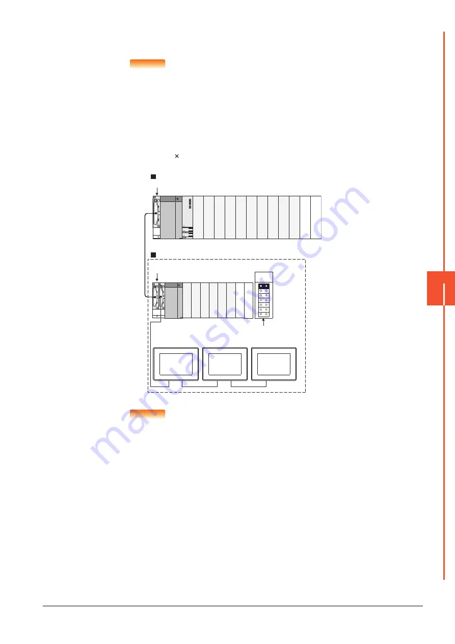
(1) When connecting to QCPU (Q mode)
Set an additional stage (16 points 10 slots) for GOT connection, and assign a GOT to one of the I/O slots.
(The GOT cannot be assigned to empty slots of the main base unit or extension base unit.)
POINT
POINT
POINT
When using the bus extension connector box
Set the Stage No. switch on the bus extension connector box to the same Stage No. as the GOT.
For setting details, refer to the following manual:
➠
A9GT-QCNB Bus Extension Connector Box User's Manual
Q312B
Q68B
Main base unit
Stage No. :2
Slot No. :0
Stage No. :2
Slot No. :1
Stage No. :2
Slot No. :2
Extension base unit
Stage No. setting
connector
Extension
stage 1
Empty
Empty
Empty
Empty
Summary of Contents for GOT2000 Series
Page 2: ......
Page 84: ......
Page 432: ...6 58 6 6 Precautions ...
Page 578: ...9 54 9 6 Precautions ...
Page 726: ...12 84 12 5 Precautions ...
Page 756: ......
Page 822: ...14 66 14 4 Device Range that Can Be Set ...
Page 918: ...15 96 15 7 Precautions ...
Page 930: ...16 12 16 6 Precautions ...
Page 964: ......
Page 1002: ...19 38 19 7 Precautions ...
Page 1022: ...20 20 20 5 Precautions ...
Page 1023: ...MULTI CHANNEL FUNCTION 21 MULTI CHANNEL FUNCTION 21 1 ...
Page 1024: ......
Page 1054: ...21 30 21 5 Multi channel Function Check Sheet ...
Page 1055: ...FA TRANSPARENT FUNCTION 22 FA TRANSPARENT FUNCTION 22 1 ...
Page 1056: ......
Page 1223: ......


