9 - 36
9.5 PLC side setting when connecting to MELSEC/10
9.5.2
Connecting to MELSECNET/10 network module (QnA Series)
This section describes the settings of the GOT and MELSECNET/10 network module (QnA series) in the following case of
system configuration.
In this section, the network parameter (common parameter) of GX Developer is taken as an example to provide
explanations.
POINT
POINT
POINT
MELSECNET/10 network module (QnA Series)
For details of the MELSECNET/10 network module (QnA Series), refer to the following manual.
➠
For QnA/Q4AR MELSECNET/10 Network System Reference Manual
■1.
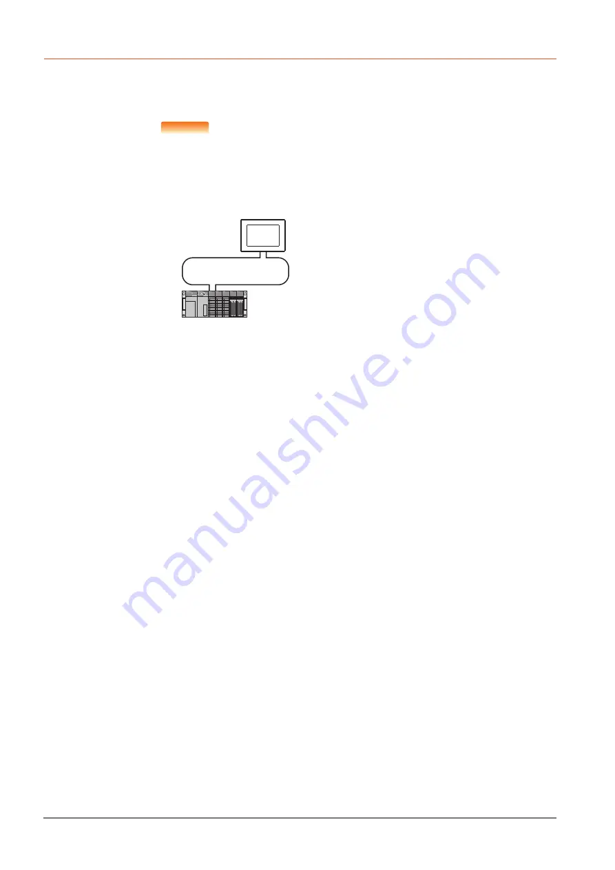
System configuration
*1
The MELSECNET/10 network module is mounted at slot 0 of the base unit.
The start I/O No. of the MELSECNET/10 network module is set at "0".
<MELSECNET/10 network module> *1
(Use the default value for settings other than the following.)
Station No.
Mode
Network type
Network No.
Total stations
Network range assignment: B0000
H
to B00FF
H
W0000
H
to W00FF
H
MELSECNET/10 (PLC to PLC network)
<GOT>
(Use the default value for settings other
than the following.)
Station No.
Mode
Network No.
Network range assignment: B0100
H
to B01FF
H
: 2
: Online
: 1
: 1
: 1
: 2
: Online
: MNET/10 (Control station)
W0100
H
to W01FF
H
Summary of Contents for GOT2000 Series
Page 2: ......
Page 84: ......
Page 432: ...6 58 6 6 Precautions ...
Page 578: ...9 54 9 6 Precautions ...
Page 726: ...12 84 12 5 Precautions ...
Page 756: ......
Page 822: ...14 66 14 4 Device Range that Can Be Set ...
Page 918: ...15 96 15 7 Precautions ...
Page 930: ...16 12 16 6 Precautions ...
Page 964: ......
Page 1002: ...19 38 19 7 Precautions ...
Page 1022: ...20 20 20 5 Precautions ...
Page 1023: ...MULTI CHANNEL FUNCTION 21 MULTI CHANNEL FUNCTION 21 1 ...
Page 1024: ......
Page 1054: ...21 30 21 5 Multi channel Function Check Sheet ...
Page 1055: ...FA TRANSPARENT FUNCTION 22 FA TRANSPARENT FUNCTION 22 1 ...
Page 1056: ......
Page 1223: ......