9.5 PLC side setting when connecting to MELSEC/10
9 - 37
MELSECNET/H C
O
NNE
CTION (PLC T
O
PLC N
ETWORK),
MELSECNET/10 CONNECTION (PLC T
O
PLC NETWORK)
9
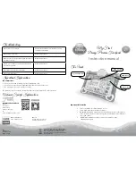
■2.
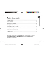
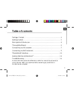
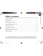
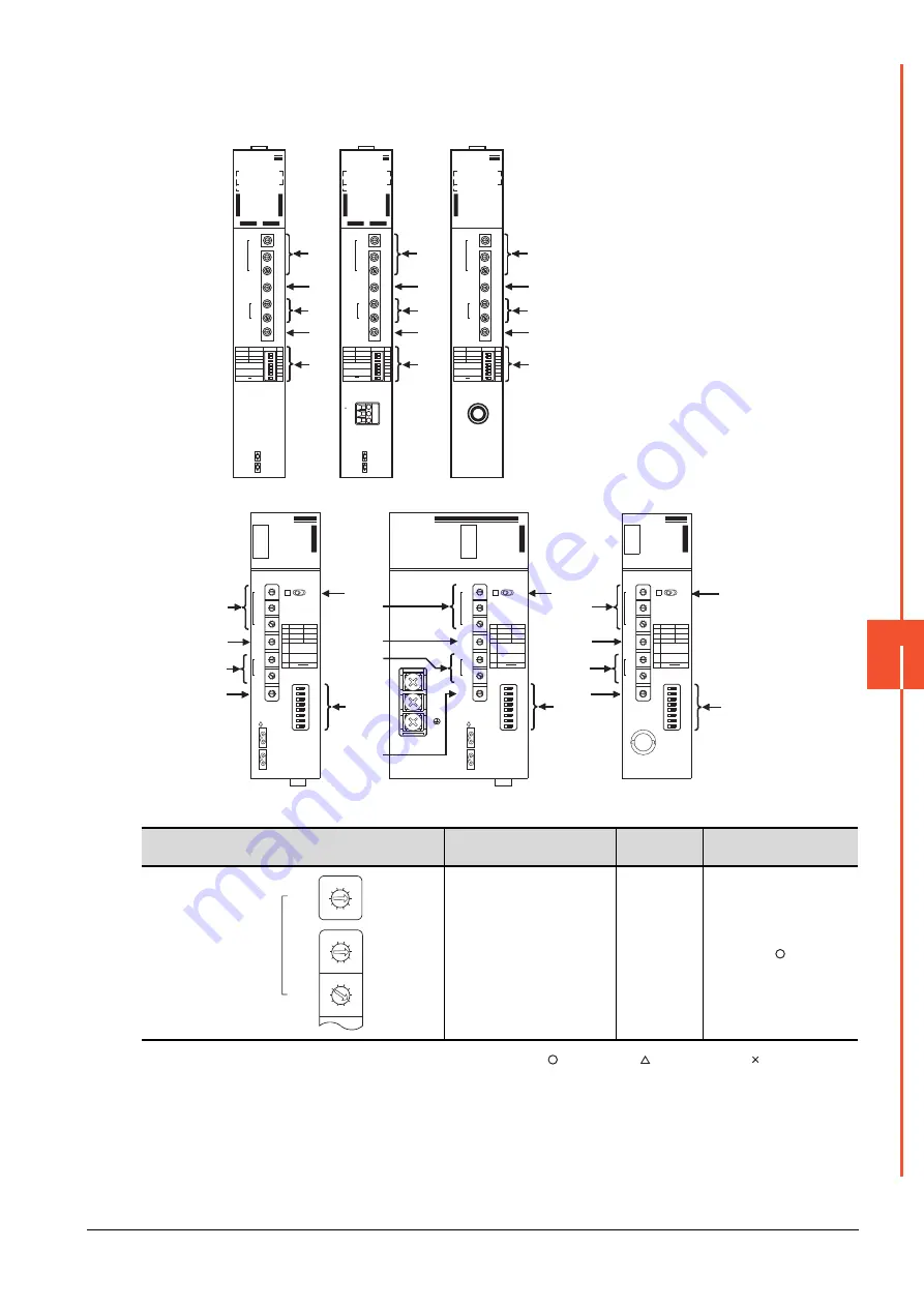
Switch setting of MELSECNET/10 network module
Set for each setting switch.
(1) Network number setting switch
: Necessary : As necessary : Not necessary
*1
Specify the same network No. as that of the GOT.
Network number
setting switch
Description
Set value
Setting necessity at GOT
connection
Network No. setting
(Network No.1)
*1
1
IN
FRONT SIDE
OUT
NETWORK NO.
X100
X10
X1
GROUP NO.
STATION NO.
X10
X1
MODE
0: ONLINE(A.R)
2: OFFLINE
OFF
PC
REMOTE
N.ST
MNG
PRM
D.PRM
STATION SIZE
(8.16.32.64)
LB/LW SIZE
(2.4.6.8K)
OFF
ON
ON SW
1
2
3
4
5
6
7
8
A
J71QLP21
RUN -
PC -
REMOTE -
DUAL -
SW.E -
M/S.E -
PRM.E -
CRC -
OVER -
AB.IF -
TIME -
DATA -
UNDER -
LOOP -
SD -
RD -
- POWER
- MNG
- S.MNG
- D.LINK
- T.PASS
-
- CPUR/W
- CRC
- OVER
- AB.IF
- TIME
- DATA
- UNDER
- LOOP
- SD
- RD
F.LOOP
R.LOOP
10
1
100
E
R
R
O
R
E
R
R
O
R
(1)
(2)
(6)
(3)
(5)
AJ71QLP21
NETWORK NO.
X100
X10
X1
GROUP NO.
STATION NO.
X10
X1
MODE
0: ONLINE(A.R)
2: OFFLINE
OFF
PC
REMOTE
N.ST
MNG
PRM
D.PRM
STATION SIZE
(8.16.32.64)
LB/LW SIZE
(2.4.6.8K)
OFF
ON
ON SW
1
2
3
4
5
6
7
8
A
J71QBR11
RUN -
PC -
REMOTE -
SW.E -
M/S.E -
PRM.E -
CRC -
OVER -
AB.IF -
TIME -
DATA -
UNDER -
SD -
RD -
- POWER
- MNG
- S.MNG
- D.LINK
- T.PASS
-
- CPUR/W
10
1
100
E
R
R
O
R
(1)
(2)
(6)
(3)
(5)
AJ71QBR11
A1SJ71QLP21
A1SJ71QLP21
3
2
0
5
9
4
8
7
6
1
3
2
0
5
9
4
8
7
6
1
3
2
0
5
9
4
8
7
6
1
3
2
0
5
9
4
8
7
6
1
3
2
0
5
9
4
8
7
6
1
3
2
0
5
9
4
8
7
6
1
SW
1
2
3
4
5
6
7
8
OFF
PC
N.ST
PRM
ON
REM.
MNG
D.PRM
ST,SIZE
8,16,32,64
LB/LW SIZE
2,4,6,8k
CRC
OVER
AB. IF
TIME
DATA
UNDER
SD
RD
PW
PC
REM.
SWE.
M/S.E.
PRM E.
R.E.
CPU R/W
RUN
MNG
S.MNG
DUAL
D.LINK
T.PASS
F.E.
‚d
‚q
‚q
‚n
‚q
L
R
DISPLAY
(F.L) (R.L.)
NETWORK
NO.
X100
X10
X1
OFF ON
IN
FRONT SIDE
OUT
SW
1
2
3
4
5
6
7
8
GR.NO.
ST.NO.
X10
X1
MODE
MODE
0 : ONLINE(A.R)
2 : OFFLINE
E
6
D
5
C
4
B
3
A
2
9
1
8
0F
7
(6)
(4)
(1)
(2)
(3)
(5)
A1SJ71QLP21
A1SJ71QLP21S
A1SJ71QLP21S
3
2
0
5
9
4
8
7
6
1
3
2
0
5
9
4
8
7
6
1
3
2
0
5
9
4
8
7
6
1
3
2
0
5
9
4
8
7
6
1
3
2
0
5
9
4
8
7
6
1
3
2
0
5
9
4
8
7
6
1
SW
1
2
3
4
5
6
7
8
OFF
PC
N.ST
PRM
ON
REM.
MNG
D.PRM
ST,SIZE
8,16,32,64
LB/LW SIZE
2,4,6,8k
CRC
OVER
AB. IF
TIME
DATA
UNDER
SD
RD
RUN
MNG
S.MNG
DUAL
D.LINK
T.PASS
F.E.
‚d
‚q
‚q
‚n
‚q
L
R
DISPLAY
(F.L) (R.L.)
NETWORK
EXT.P W
NO.
X100
X10
X1
OFF ON
IN
FRONT SIDE
EXT.PW
{24V
24G
FG
OUT
SW
1
2
3
4
5
6
7
8
GR.NO.
ST.NO.
X10
X1
MODE
MODE
0 : ONLINE(A.R)
2 : FOFFLINE
PW
PC
REM.
SWE.
M/S.E.
PRM E.
R.E.
CPU R/W
E
6
D
5
C
4
B
3
A
2
9
1
8
0F
7
(6)
(4)
(1)
(2)
(3)
(5)
A1SJ71QLP21S
L
R
DISPLAY
(F.L) (R.L.)
A1SJ71QBR11
A1SJ71QBR11
3
2
0
5
9
4
8
7
6
1
3
2
0
5
9
4
8
7
6
1
3
2
0
5
9
4
8
7
6
1
3
2
0
5
9
4
8
7
6
1
3
2
0
5
9
4
8
7
6
1
3
2
0
5
9
4
8
7
6
1
SW
1
2
3
4
5
6
7
8
OFF
PC
N.ST
PRM
ON
REM.
MNG
D.PRM
ST,SIZE
8,16,32,64
LB/LW SIZE
2,4,6,8k
CRC
OVER
AB. IF
TIME
DATA
UNDER
SD
RD
PW
PC
REM.
SWE.
M/S.E.
PRM E.
CPU R/W
RUN
MNG
S.MNG
D.LINK
T.PASS
‚d
‚q
‚q
‚n
‚q
NETWORK
NO.
X100
X10
X1
OFF ON
SW
1
2
3
4
5
6
7
8
GR.NO.
ST.NO.
X10
X1
MODE
MODE
0 : ONLINE (A.R)
2 : OFFLINE
E
6
D
5
C
4
B
3
A
2
9
1
8
0F
7
(6)
(4)
(1)
(2)
(3)
(5)
A1SJ71QBR11
IN
24V
24G
FG
FRONT SIDE
OUT
NETWORK NO.
X100
X10
X1
GROUP NO.
STATION NO.
X10
X1
MODE
0: ONLINE(A.R)
2: OFFLINE
OFF
PC
REMOTE
N.ST
MNG
PRM
D.PRM
STATION SIZE
(8.16.32.64)
LB/LW SIZE
(2.4.6.8K)
OFF
ON
ON SW
1
2
3
4
5
6
7
8
A
J71QLP21S
RUN -
PC -
REMOTE -
DUAL -
SW.E -
M/S.E -
PRM.E -
CRC -
OVER -
AB.IF -
TIME -
DATA -
UNDER -
LOOP -
SD -
RD -
- POWER
- MNG
- S.MNG
- D.LINK
- T.PASS
- EX.POWER
- CPUR/W
- CRC
- OVER
- AB.IF
- TIME
- DATA
- UNDER
- LOOP
- SD
- RD
F.LOOP
R.LOOP
10
1
100
E
R
R
O
R
E
R
R
O
R
(1)
(2)
(6)
(3)
(5)
AJ71QLP21S
3
2
0
5
9
4
8
7
6
1
3
2
0
5
9
4
8
7
6
1
3
2
0
5
9
4
8
7
6
1
NETWORK NO.
X100
X10
X1
Summary of Contents for GOT2000 Series
Page 2: ......
Page 84: ......
Page 432: ...6 58 6 6 Precautions ...
Page 578: ...9 54 9 6 Precautions ...
Page 726: ...12 84 12 5 Precautions ...
Page 756: ......
Page 822: ...14 66 14 4 Device Range that Can Be Set ...
Page 918: ...15 96 15 7 Precautions ...
Page 930: ...16 12 16 6 Precautions ...
Page 964: ......
Page 1002: ...19 38 19 7 Precautions ...
Page 1022: ...20 20 20 5 Precautions ...
Page 1023: ...MULTI CHANNEL FUNCTION 21 MULTI CHANNEL FUNCTION 21 1 ...
Page 1024: ......
Page 1054: ...21 30 21 5 Multi channel Function Check Sheet ...
Page 1055: ...FA TRANSPARENT FUNCTION 22 FA TRANSPARENT FUNCTION 22 1 ...
Page 1056: ......
Page 1223: ......